A linear cutting stapler with stroke indicating device

An indicating device, a straight-line cutting technology, applied in the direction of surgical fixation nails, etc., can solve the problems of inconvenient surgical operation, inability to clearly display the stroke of the cutter and the firing piece, and inconvenience.

Active Publication Date: 2014-10-01
B J ZH F PANTHER MEDICAL EQUIP
View PDF4 Cites 0 Cited by
  • Summary
  • Abstract
  • Description
  • Claims
  • Application Information

AI Technical Summary

Problems solved by technology

However, in actual operation, it is found that the existing common linear cutting stapler cannot clearly display the stroke of the cutting knife and firing piece, so it is very inconvenient for the operation
[0004] This shows that the above-mentioned existing linear cutting stapler obviously still has inconvenience and defects in structure and use, and needs to be further improved urgently.

Method used


Image

  • A linear cutting stapler with stroke indicating device
  • A linear cutting stapler with stroke indicating device
  • A linear cutting stapler with stroke indicating device

Examples


Embodiment 1

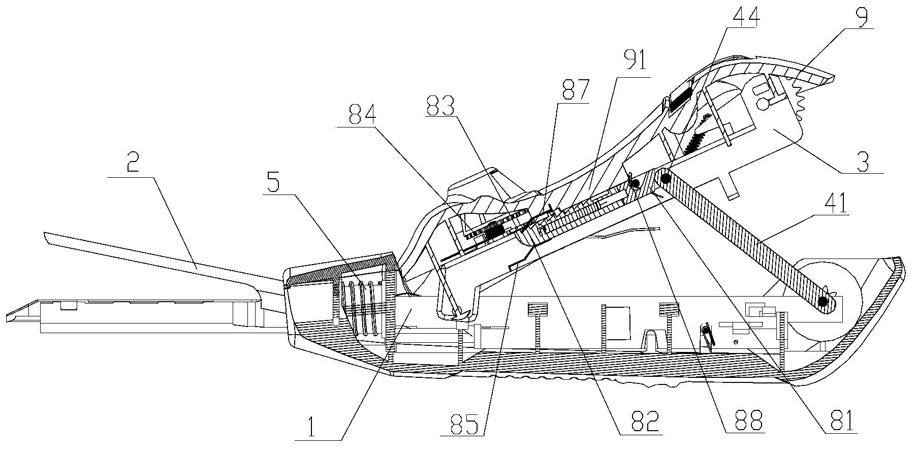
[0031] see figure 1 As shown, a linear cutting stapler with a stroke indicating device of the present invention mainly includes a fixed splint 1, an abutment seat assembly 2, a closing splint 3, a transmission mechanism, a guide bar 81, a stroke block 82, a transmission gear 83 and an indication Wheel 84.

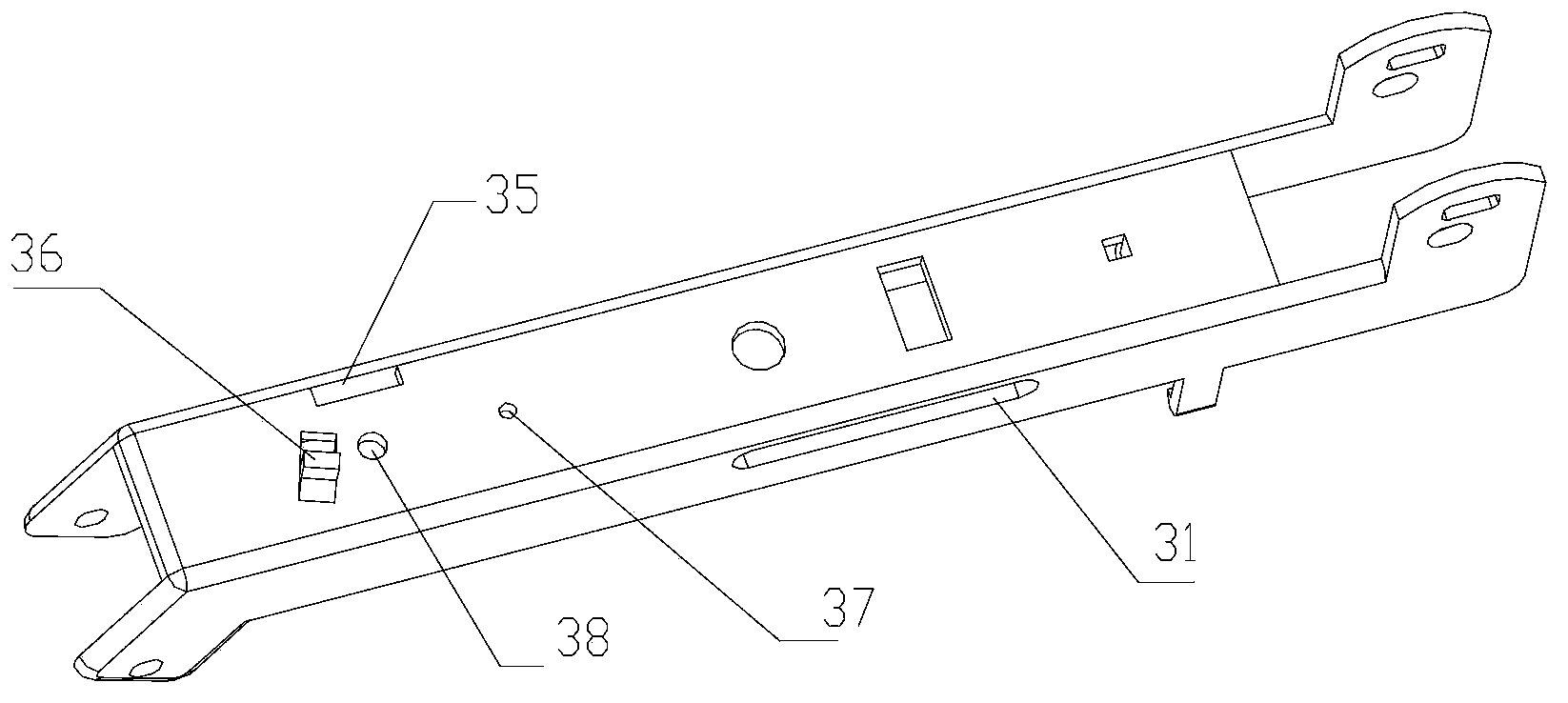
[0032] Among them, please refer to figure 2 As shown, one side of the closing splint 3 is provided with a chute 31, and the upper surface is provided with a transmission gear mounting hole 37 and an indicator wheel mounting hole 38. Turn to connect.

[0033] The transmission gear 83 and the indicator wheel 84 are rotatably installed on the upper surface of the closing splint 3 through the transmission gear installation hole 37 and the indicator wheel installation hole 38 .

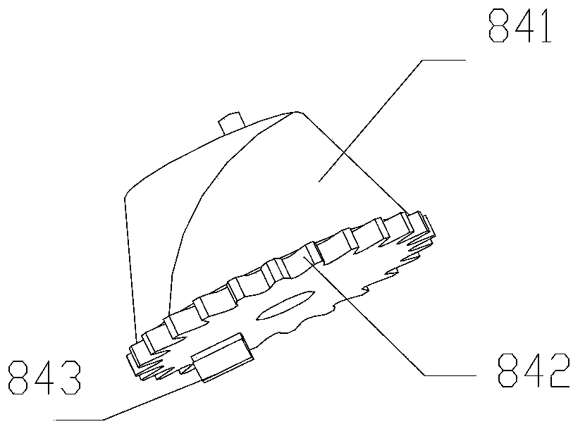
[0034] Please refer to image 3 As shown, the indicating wheel 84 is provided with an indicating surface 841 and is meshed with the transmission gear 83 through the ratchet 842. The indicating surf...

Embodiment 2

[0040] Such as figure 1 As shown, on the basis of Embodiment 1, the stapler of the present invention can also include a movable handle 9, and the above-mentioned closing splint 3, guide bar 81, stroke block 82, transmission gear 83, and indicator wheel 84 are all installed on the movable handle 9. In the inner cavity of the closed splint 3 is fixedly connected with the movable handle 9, and the indicating surface 841 of the indicating wheel 84 can protrude from the movable handle 9.

[0041] Please refer to Figure 5-8As shown, a block 88 is rotatably installed at the rear upper end of the guide bar 81, and is provided with a block groove 811 that prevents the block 88 from rotating counterclockwise. One side of the block 88 can be provided with a limit step 881, and the block 88 is fixed by a torsion spring, one end of the torsion spring is against the limit step 881 of the block 88, and the other end is against the stop of the guide bar 81. The end face of the block groove...

Embodiment 3

[0046] Please refer to Figure 9 As shown, on the basis of Embodiment 1, the transmission gear 83 of the present invention can also be designed to be composed of large and small gears, wherein the small gear 831 is located at the upper end and meshes with the indicator wheel 84; the large gear 832 is located at the lower end and is connected to the stroke block. The rows of teeth 821 of 82 mesh.


PUM


Abstract

The invention relates to a linear cutting stitching instrument with a travel indicating device. The linear cutting stitching instrument comprises a fixed clamping plate, a closed clamping plate, a nail pressing seat assembly, a transmission mechanism, a conducting bar, a travel block, a transmission gear and an indicating wheel; one side of the closed clamping plate is provided with a chute; the transmission mechanism comprises a supporting connecting rod, a push knife connecting rod and a band knife rack; the front end of the supporting connecting rod is rotatably connected with the rear end of the push knife connecting rod through a pin shaft capable of sliding forwards and backwards along the chute; the transmission gear and the indicating wheel are rotatably arranged on the upper surface of the closed clamping plate, and the indicating wheel is engaged with the transmission gear; and row teeth engaged with the transmission gear is arranged on the upper surface of the travel block, the conducting bar is spliced with the travel block and arranged on one side of the closed clamping plate, the front lower end of the travel block is supported by a supporting plate spring arranged on the closed clamping plate, and the rear end of the conducting bar is connected with the supporting connecting rod and the push knife connecting rod through the pin shaft. The stitching instrument can be used for facilitating an operation, is suitable for open operation of enterectomy and gastrectomy, and is simple in structure, clear in indication, light and flexible.

Description

technical field [0001] The present invention relates to a medical device for surgical operations, in particular to a device with stroke indication [0002] The linear cutting stapler of the device. Background technique [0003] The linear cutting stapler is widely used in surgical operations for wound suturing, internal tissue suturing and cutting. The linear cutting stapler has two functions of suturing and cutting, and the excess tissue is removed while suturing the wound. This type of linear incision stapler generally includes upper and lower jaws, and a closing handle for closing the upper and lower jaws. The firing piece and the cutting knife in the magazine can move relative to the staple cartridge at the same time, and the push torque for driving the firing piece and the cutting knife to move. Staples are arranged in the staple cartridge, and the firing piece pushes the staple pusher in turn and pushes the staples to the staple abutment seat, and the cutter cuts off...

Claims


Application Information

Patent Timeline
Patent Type & Authority Patents(China)
IPC IPC(8): A61B17/072
CPCA61B17/07207
Inventor 李学军刘青
Owner B J ZH F PANTHER MEDICAL EQUIP
Why Eureka
Try Eureka