Automatic container loader for solar energy component
A technology of solar modules and packing machines, which is applied in the directions of automatic packaging control, packaging, and packaging protection. It can solve the problems of large number of workers, low packing efficiency, and difficult operation, so as to save human resources and improve production efficiency. Effect
- Summary
- Abstract
- Description
- Claims
- Application Information
AI Technical Summary
Problems solved by technology
Method used
Image

Examples
Embodiment 1
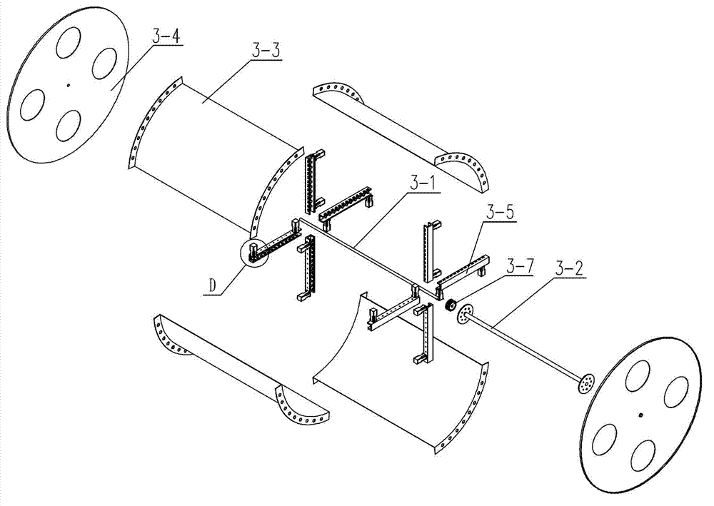
[0036] Embodiment one: if figure 1 figure 2 As shown, an automatic packing machine for solar modules has a clamping roller 3 that can clamp and rotate solar components 6 . The clamping drum 3 has a drum shaft 3-1, a drum pulley 3-7, an inner connecting frame 3-2, end plates 3-4 located on both sides, and four sets of symmetrically assembled clampers 3-5. Four holders 3-5 are installed on each end plate 3-4, and the corresponding holders 3-5 on the end plates 3-4 on both sides are used as a group.
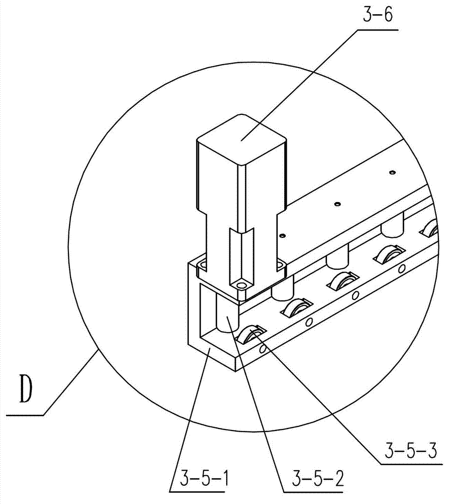
[0037]The drum pulley 3-7 is connected to the drum shaft 3-1, the inner connecting frame 3-2 is sheathed on the drum shaft 3-1, the two ends of the inner connecting frame 3-2 are respectively connected to the end plate 3-4, and the drum pulley 3- 7 is located on the outside of any end plate 3-4, the clamper 3-5 has a clamping bracket 3-5-1, and the clamping bracket 3-5-1 is provided with a card slot that can clamp the solar module 6, and the clamping bracket 3-5-1 The bottom or ...
Embodiment 2
[0041] Embodiment two, such as Figure 10 Figure 11 Figure 12 Figure 13 Figure 14 Figure 15 As shown, this embodiment is a further more automated implementation.
[0042] An automatic packing machine for solar modules has a clamping roller 3, which can clamp and rotate solar components. The structure of the clamping roller in this embodiment is basically the same as the structure of the clamping roller in the first embodiment.
[0043] The clamping drum 3 has a drum shaft 3-1, a drum pulley 3-7, an inner connecting frame 3-2, end plates 3-4 located on both sides, and four sets of symmetrically assembled clampers 3-5. Four holders 3-5 are installed on each end plate 3-4, and the corresponding holders 3-5 on the end plates 3-4 on both sides are used as a group.
[0044] The drum pulley 3-7 is connected to the drum shaft 3-1, the inner connecting frame 3-2 is sheathed on the drum shaft 3-1, the two ends of the inner connecting frame 3-2 are respectively connected to t...
PUM
 Abstract
Description
Claims
Application Information
 - Generate Ideas
- Intellectual Property
- Life Sciences
- Materials
- Tech Scout
- Unparalleled Data Quality
- Higher Quality Content
- 60% Fewer Hallucinations
Browse by: Latest US Patents, China's latest patents, Technical Efficacy Thesaurus, Application Domain, Technology Topic, Popular Technical Reports.
© 2025 PatSnap. All rights reserved.Legal|Privacy policy|Modern Slavery Act Transparency Statement|Sitemap|About US| Contact US: help@patsnap.com