Novel centrifugal fan

A centrifugal fan, a new type of technology, applied in conveyors, transportation and packaging, conveying bulk materials, etc., can solve the problems of shortening the service life of the casing, affecting the operation of the system, destroying the balance, etc., to achieve stable fan performance and reduce eddy current noise. , the effect of prolonging the service life

Inactive Publication Date: 2012-12-12
ZHEJIANG XINGYI VENTILATOR ELECTRICAL APPLIANCE
View PDF4 Cites 4 Cited by
  • Summary
  • Abstract
  • Description
  • Claims
  • Application Information

AI Technical Summary

Problems solved by technology

[0006] In order to prolong the life of the impeller, the manufacturer adopts wear-resistant materials to manufacture the fan impeller, increases the thickness of the plate at the damaged part of the impeller, welds wear-resistant materials on the parts of the impeller that are prone to wear, and adds wear-resistant plates to the parts of the impeller that are partially worn. Both prolong the service life of the impeller to varying degrees. These measures are passively subjected to the impact and wear of dust, so there are no new breakthroughs.
[0007] 2. The impeller is easy to block and collect dust during work
[0008] At present, most of the impellers of this type of fan are fully closed impellers. During the process of conveying materials, the blades of this fan are easy to collect dust and block, which will destroy the balance and affect the normal operation of the fan.
[0009] 3. Low efficiency, high noise, unstable fan performance, waste of energy
[0010] a. At present, the highest efficiency of this type of fan is about 70%, the power consumption is large, and the high efficiency area is narrow, and the pressure coefficient of the large flow area is low. Therefore, when the fan operates in the large flow area, the output is often insufficient, which affects the system operation
[0011] b. There is no vortex plate at the air inlet, the efficiency of the fan is low and the vortex noise is high during the operation of the fan
[0012] 4. It is inconvenient to replace the shaft end seal
[0013] At present, the shaft end seal of this type of fan is integral. Therefore, when replacing and maintaining, the impeller must be removed to maintain, which is time-consuming and laborious, and the maintenance cost is high.
[0014] 5. The gap between the air tongue of the volute and the impeller is unreasonable, so the air flow noise is large during the operation of the fan, the tongue plate is severely worn, and the service life of the casing is shortened

Method used


Image

  • Novel centrifugal fan
  • Novel centrifugal fan

Examples


Embodiment Construction

[0045] The following are specific embodiments of the present invention and in conjunction with the accompanying drawings, the technical solutions of the present invention are further described, but the present invention is not limited to these embodiments.

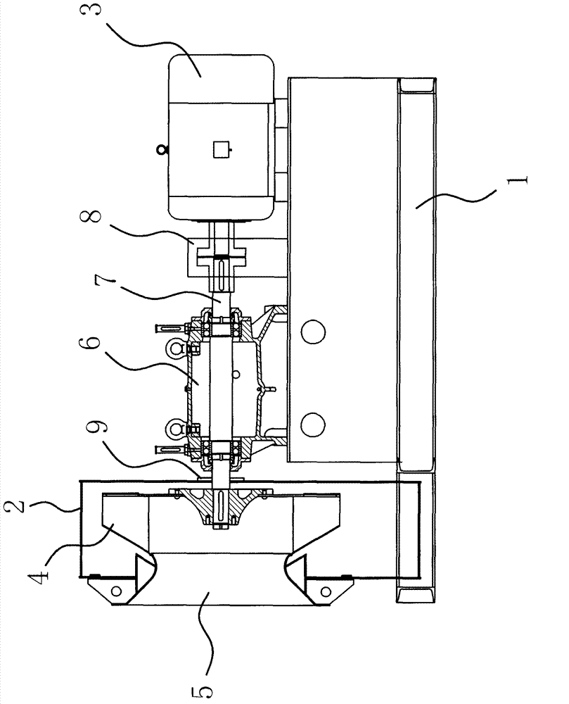
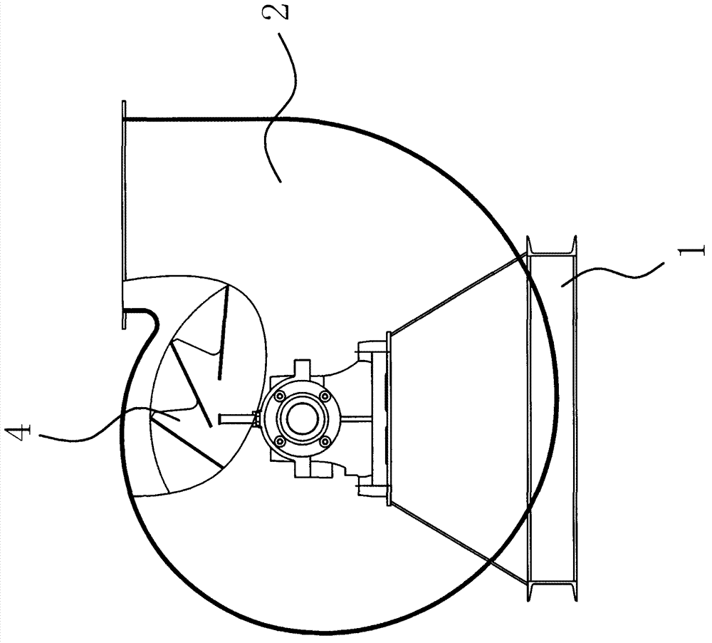
[0046] like figure 1 As shown, the centrifugal fan includes a frame 1, a volute housing 2 with an air inlet and an air outlet located at the frame 1, and a motor 3 located on the frame 1, and the air inlet is located at the volute housing 2 The side of the volute housing 2 is provided with an impeller 4 driven by a motor 3 . like figure 1 As shown, a bearing housing 6 is provided on the frame 1 between the motor 3 and the volute housing 2, and a main shaft 7 is pierced in the bearing housing 6, and one end of the main shaft 7 is connected to the output shaft of the motor 3 through a coupling 8. , the other end of the main shaft 7 protrudes into the side wall of the volute housing 2, and the impeller 4 is sleeved on the m...


PUM


Abstract

The invention provides a novel centrifugal fan and belongs to the technical field of fans. The novel centrifugal fan solves the problems of proneness to dust accumulation and short service life of existing centrifugal fans, and comprises a frame, a volute casing and a motor. The volute casing which is provided with an air inlet and an air outlet is arranged at the frame, the motor is disposed on the frame, the air inlet is positioned on the side of the volute casing, and an impeller driven by the motor is arranged in the volute casing. One side, positioned at the air inlet, of the impeller is ratchet-shaped. A conical rectifying barrel is arranged at the air inlet. The novel centrifugal fan has the advantages of long service life, high pneumatic performance and efficiency and the like.

Description

technical field [0001] The invention belongs to the technical field of fans, and relates to a centrifugal fan, in particular to a novel centrifugal fan used for conveying high dust or materials. Background technique [0002] The centrifugal fan is a machine that relies on the input mechanical energy to increase the gas pressure and discharge the gas. It is a driven fluid machine. Centrifugal fans are widely used in factories, mines, tunnels, cooling towers, vehicles, ships and buildings for ventilation, dust removal and cooling and material transportation, as well as ventilation and drafting of boilers and industrial furnaces, air conditioning equipment and household appliances Cooling and ventilation in the middle, as well as drying and selection of grains, etc. As we all know, a centrifugal fan generally includes a shell with a spiral air duct, an outlet at the end, and an air inlet in the middle of the spiral air duct. The centrifugal fan also includes an impeller and a ...

Claims


Application Information

Patent Timeline
Patent Type & Authority Applications(China)
IPC IPC(8): B65G53/50
Inventor 徐经存
Owner ZHEJIANG XINGYI VENTILATOR ELECTRICAL APPLIANCE
Why Eureka
Try Eureka