Exhaust control system used for sanitation system

A control system and hygienic technology, applied in pump control, sanitary equipment for toilets, non-variable-capacity pumps, etc., can solve problems such as pollution, affecting people's living conditions, etc. Simple circuit effect

Active Publication Date: 2012-12-12
宜昌兆峰自动化仪表有限责任公司
View PDF5 Cites 2 Cited by
  • Summary
  • Abstract
  • Description
  • Claims
  • Application Information

AI Technical Summary

Problems solved by technology

[0002] With the development of the economy, the improvement of people's living standards, and the improvement of the hardware conditions of families or public places, the facilities of the bathroom in buildings or rooms are an important link that affects the comfort of living. The fan discharges outdoors, the pollution problem cannot be completely solved, and it affects people's living conditions

Method used


Image

  • Exhaust control system used for sanitation system
  • Exhaust control system used for sanitation system

Examples


Embodiment Construction

[0017] Embodiments of the present invention will be further described below in conjunction with the accompanying drawings.

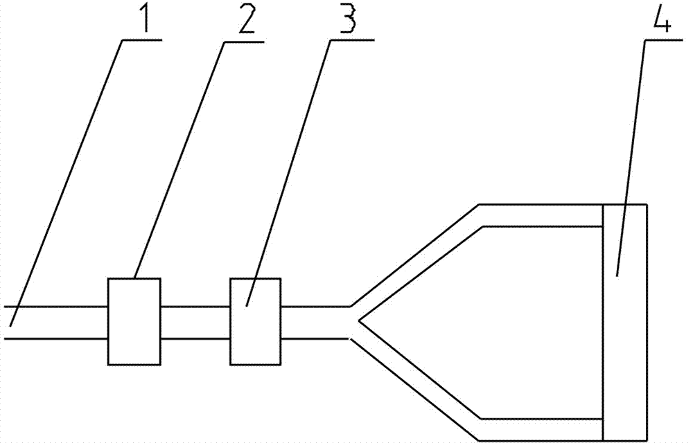
[0018] The structure diagram of the exhaust control system is shown in figure 1 shown. The exhaust control system includes an exhaust pipe 1, a desiccant 2, a catalytic converter 3 and an exhaust fan 4. The catalyst and desiccant are installed in the exhaust pipe to process the gas discharged through the exhaust pipe. In addition, the system also includes a circuit (not shown) for controlling the exhaust fan.

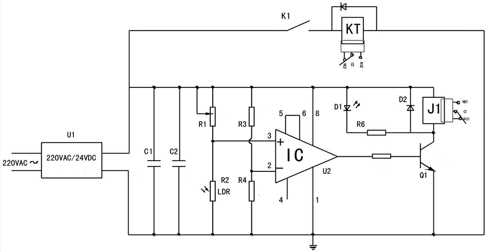
[0019] The circuit that controls the exhaust fan in the exhaust control system is as follows: figure 2 shown. The circuit includes a power module U1, an electromagnetic relay J1, a time relay KT, a switch K1, a piezoresistor R2, a triode Q1 and a voltage comparator U2. Among them, a group of normally closed contacts of the time relay KT is connected in series to the power supply circuit of the exhaust fan, the time relay KT is connected in se...


PUM


Abstract

The invention discloses an exhaust control system used for a sanitation system. The exhaust control system comprises an exhaust fan, a power supply module U1, an electromagnetic relay J1, a time relay KT, a switch K1, a pressure-sensitive resistor R2, a triode Q1 and a voltage comparator U2, wherein a group of normally closed contacts of the time relay KT are connected with a power supply loop of the exhaust fan in series, and a group of normally opened contacts of the electromagnetic relay J1 are connected to the power supply loop of the exhaust fan in series. The exhaust control system further comprises an exhaust pipeline, a drying agent and a catalyst, wherein the catalyst and the drying agent are arranged in the exhaust pipeline, and gas discharged by the exhaust pipeline is processed. The system has the advantages of simple circuit, low cost, strong operability, and capability of automatically removing dirty gas in the room and a closestool, purifying indoor environment and improving the toilet entrance environment.

Description

technical field [0001] The invention relates to the technical field of exhaust control used in sanitary systems in households or public places, in particular to an exhaust control system for sanitary systems. Background technique [0002] With the development of the economy, the improvement of people's living standards, and the improvement of the hardware conditions of families or public places, the facilities of the bathroom in buildings or rooms are an important link that affects the comfort of living. The fan discharges the air outside, and the pollution problem cannot be completely solved, which affects people's living conditions. Therefore, how to improve the air condition in the bathroom, so that no peculiar smell can be smelled in the bathroom, and zero pollution is achieved, thereby improving people's quality of life and health level, has become an urgent technical problem to be solved. Contents of the invention [0003] In view of the above defects in the prior a...

Claims


Application Information

Patent Timeline
Patent Type & Authority Applications(China)
IPC IPC(8): E03D9/052F04D27/00
Inventor 熊章华张兆峰
Owner 宜昌兆峰自动化仪表有限责任公司
Why Eureka
Try Eureka