
Chain transmission speed changing box mechanism

A gearbox and chain transmission technology, which is applied to transmission devices, transmission device parts, mechanical equipment, etc., can solve the problems of difficult gear manufacturing and high cost, and achieve the effect of great economic benefits

Inactive Publication Date: 2012-12-12
HENAN UNIV OF SCI & TECH
View PDF7 Cites 2 Cited by
  • Summary
  • Abstract
  • Description
  • Claims
  • Application Information

AI Technical Summary

Problems solved by technology

In addition, although the whole mechanism is relatively stable with gear transmission, the manufacturing of gears is relatively difficult and the cost is high, so it is suitable for important working machines or occasions.

Method used


Image

  • Chain transmission speed changing box mechanism

Examples


Embodiment Construction

[0011] The present invention can be explained in more detail by referring to the accompanying drawings and the following embodiments, and the present invention is not limited to the combination of the following embodiments.

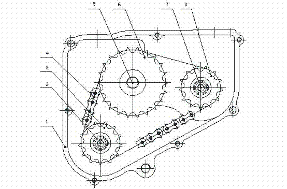
[0012] As shown in the figure, a chain transmission gearbox mechanism includes a gearbox housing 1 and a power input shaft 5, and a power input shaft sprocket 6, a lower drive shaft sprocket 3, and an upper drive shaft are arranged in the gearbox housing 1. Shaft sprocket 8 and chain 4, power input shaft sprocket 6, lower drive shaft sprocket 3 and upper drive shaft sprocket 8 are triangularly distributed and arranged in a plane, and chain 4 bypasses power input shaft sprocket 6, The lower drive shaft sprocket 3 and the upper drive shaft sprocket 8 form a closed loop, the power input shaft sprocket 6 is arranged on the power input shaft 5, and the lower drive shaft sprocket 3 and the upper drive shaft sprocket 8 are respectively arranged on the lower drive...


PUM


Abstract

The invention relates to a chain transmission speed changing box mechanism comprising a speed changing box shell and a power input shaft, wherein a power input shaft chain wheel, a lower drive shaft chain wheel, an upper drive shaft chain wheel and a chain are arranged in the speed changing box shell, the power input shaft chain wheel, the lower drive shaft chain wheel and the upper drive shaft chain wheel are distributed in a triangular shape and arranged in a plane, the chain sequentially bypasses the power input shaft chain wheel, the lower drive shaft chain wheel and the upper drive shaft chain wheel to form a closed loop, the power input shaft chain wheel is arranged on the power input shaft, and the lower drive shaft chain wheel and the upper drive shaft chain wheel are respectively and correspondingly arranged on a lower drive shaft and an upper drive shaft. The speed changing box mechanism reduces processing difficulty and production cost by using the chain wheels for replacing gears, increases transmission distance and saves transmission stages by using chain transmission for replacing gear transmission.

Description

technical field [0001] The invention relates to a speed change mechanism with single power input and double power output, in particular to a chain transmission gearbox mechanism. Background technique [0002] Machines are an important tool in the development of modern society. The gearbox is one of the important parts in a machine, that is to say, when a machine is invented and created, there is a gearbox to determine its certain working process. [0003] Now with the gradual development of the machine, the types of gearboxes have also become diverse. However, the structure of the gearbox of most machines is mostly a combination of a shell, a gear set and a gear shaft according to certain rules. The technology of this kind of gearbox is relatively mature. Although the appearance is various, the internal structure is basically the same Yes, people are familiar with the production and manufacture of this kind of gearbox, so this kind of gearbox is mostly used in machines. U...

Claims


Application Information

Patent Timeline
Patent Type & Authority Applications(China)
IPC IPC(8): F16H7/06F16H57/035
Inventor 姬江涛郑治华杜新武贺智涛何亚凯刘剑君杜蒙蒙马俊伟
Owner HENAN UNIV OF SCI & TECH
Learn More