Eureka AIR delivers breakthrough ideas for toughest innovation challenges, trusted by R&D personnel around the world.

Method and device for automatically detecting and compensating zero position deviation of rotary transformer

A resolver and zero deviation technology, applied in the field of detecting and compensating resolver zero deviation, can solve the problems of difficult engineering implementation, large measurement error, high hardware requirements, and achieve the effects of low cost, convenient operation and strong adaptability

Inactive Publication Date: 2012-12-12
NORTHWESTERN POLYTECHNICAL UNIV
View PDF1 Cites 24 Cited by
  • Summary
  • Abstract
  • Description
  • Claims
  • Application Information

AI Technical Summary

Problems solved by technology

[0003] In order to solve the deficiencies of the existing rotary transformer zero position deviation detection method, such as large measurement error, high hardware requirements, and difficult engineering implementation, the present invention proposes a method for automatically detecting and compensating the rotary transformer zero position deviation, which can significantly simplify the detection of the rotary transformer zero position deviation. The implementation steps of position deviation reduce the difficulty of detecting the zero position deviation of the resolver, and realize the automatic compensation for the zero position deviation of the resolver. The operation is convenient, the adaptability is strong, and the cost is low

Method used


Image

  • Method and device for automatically detecting and compensating zero position deviation of rotary transformer

Examples


example

[0034] The specific implementation steps of the example are as follows:

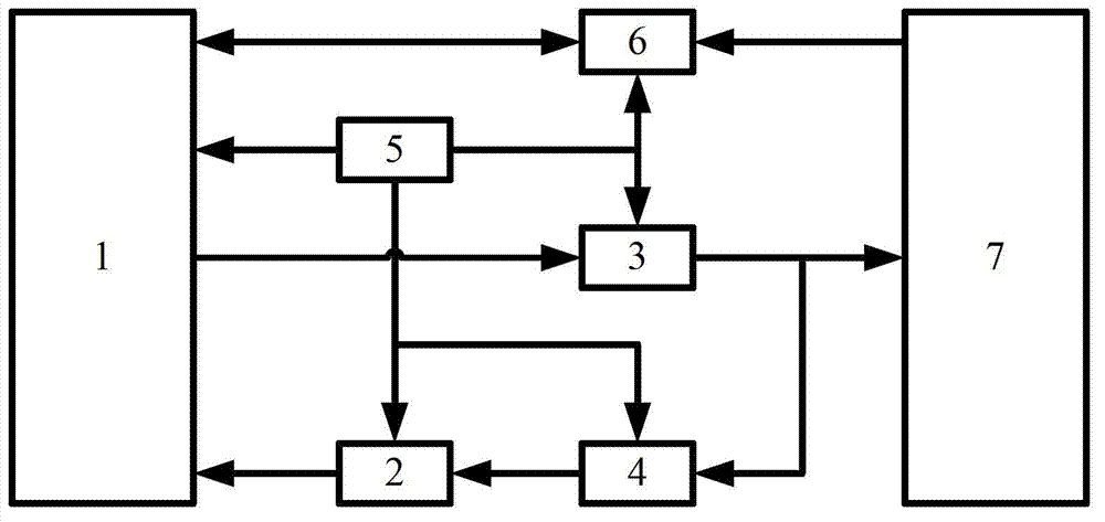
[0035] 1) The resolution circuit 6 of the resolver adopts a general-purpose 12-bit AD2S80 resolution circuit to generate a sinusoidal excitation signal of 5KHz and an effective value of 2.25V, which is sent to the resolver, and receives the output signal of the resolver for resolution. 12 channels of digital signals are sent to microcontroller 1.

[0036] 2) Microcontroller 1 sets the initial zero offset compensation value of the resolver to zero. Read the signal sent by the resolver circuit to obtain the variable RS corresponding to the rotor position of the motor, ranging from 0 to 4095. According to the value of RS, the microcontroller generates six SPWM driving signals with an amplitude modulation ratio of 0.2 through the built-in PWM module through a table look-up method, and sends them to the three-phase power driver 3 .

[0037] 3) The power drive circuit 3 connects the winding to the positive pol...


PUM


Abstract

The invention discloses a method and a device for automatically detecting and compensating the zero position deviation of a rotary transformer. After output analog signals of the rotary transformer are decoded by a signal decoding circuit of the rotary transformer, the output analog signals are sent to a microcontroller. Current of a motor phase winding is detected by a Hall current sensor, and after the current is adjusted, the current is sent to the microcontroller by an analog-digital conversion circuit. The average value of sent voltage signals is calculated by the microcontroller. According to the current phase current average value and the last zero position deviation compensation value of the rotary transformer, the direction is adjusted, and then the best zero position deviation compensation value of the rotary transformer is calculated; and meanwhile, motor control signals of the microcontroller are subjected to power amplification by a power driving circuit for driving a tested motor to normally run. According to the method and the device disclosed by the invention, zero position deviation detection implementation steps of the rotary transformer are obviously simplified, the difficulty for detecting the zero position deviation of the rotary transformer is reduced, and the automatic compensation to the zero position deviation of the rotary transformer is realized. The method and the device for automatically detecting and compensating zero position deviation of the rotary transformer also have the advantages of convenience in operation, powerful adaptability and low cost.

Description

technical field [0001] The invention relates to a method and a device for detecting and compensating the zero position deviation of a rotary transformer. Background technique [0002] The resolver has the characteristics of reliable structure, good real-time performance, and strong environmental adaptability, and is widely used in the motor servo system to accurately detect the position of the servo motor rotor. The assembly error of the resolver during installation will lead to a deviation in the zero position of the resolver, resulting in a zero position deviation between the actual rotor position of the motor and the rotor position detected through the resolver. The existence of this zero position deviation will cause unexpected and uncontrollable direct axis current, which will cause the servo motor to fail to start or reverse in severe cases. At present, the commonly used methods to detect the zero position deviation of the servo motor rotor are the pre-positioning met...

Claims


Application Information

Patent Timeline
Patent Type & Authority Applications(China)
IPC IPC(8): G01R31/00H02P6/16H02P6/185
Inventor 张玉峰李声晋魏世克杨静伟周勇张松松李鑫周广伟王严伟江修立
Owner NORTHWESTERN POLYTECHNICAL UNIV
Why Eureka
Eureka Blog
Learn More