
Seal structure, turbine machine equipped with same, and power plant equipped with said turbine machine

A sealing structure and structure technology, applied in the field of power generation equipment and turbines, can solve problems such as mixing loss and flow chaos of mainstream fluid

Active Publication Date: 2012-12-12
MITSUBISHI POWER LTD
View PDF8 Cites 1 Cited by
  • Summary
  • Abstract
  • Description
  • Claims
  • Application Information

AI Technical Summary

Problems solved by technology

Since a part of the main flow fluid is involved in the space portion 55, there is a problem that the flow of the main flow fluid is seriously disturbed and a mixing loss (mixing loss) occurs.

Method used


Image

  • Seal structure, turbine machine equipped with same, and power plant equipped with said turbine machine
  • Seal structure, turbine machine equipped with same, and power plant equipped with said turbine machine
  • Seal structure, turbine machine equipped with same, and power plant equipped with said turbine machine

Examples


no. 1 approach

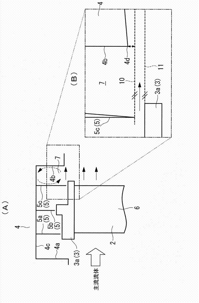
[0051] figure 1 It is the sealing structure of the gas turbine (turbine) in the power generation facility which concerns on 1st Embodiment, (A) shows the schematic structure diagram, (B) shows the partial enlarged view.

[0052] A gas turbine installed in a power generation facility has: stator blades (not shown) that direct the flow of combustion gas, that is, mainstream gas (main flow fluid) directed into the gas turbine, to a plurality of moving blades (blades) 2; The moving blade 2 on which the mainstream gas acts; the moving blade shroud 3 ( 3 a ), the moving blade shroud 3 ( 3 a ) is arranged at the front end of the moving blade 2 and each adjacent moving blade shroud 3 ( 3 a ) is in contact with each other. It is formed in a cylindrical shape; that is, a turbine housing (structural body) 4 enclosing the rotor blade 2 and the rotor blade shroud (shroud) 3 a.

[0053] The turbine casing 4 is formed in a cylindrical shape surrounding the outer periphery of a rotor blade ...

no. 2 approach

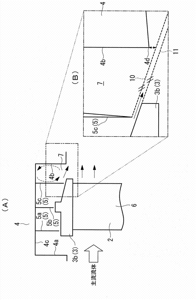
[0074] Hereinafter, a second embodiment of the present invention will be described. The sealing structure of the present embodiment, the turbine equipped with the sealing structure, and the power generation equipment equipped with the turbine are different from the first embodiment in that there is a predetermined gap between the most downstream sealing sheet (sealing unit) 5c. The outer peripheral surface on the downstream side of the rotor blade shroud that is separated by a gap gradually moves away from the inner side of the turbine housing along the flow direction of the mainstream gas acting on the rotor blades, and the rest is the same as that of the first embodiment. Therefore, the same reference numerals are attached to the same configuration and the same flow, and description thereof will be omitted.

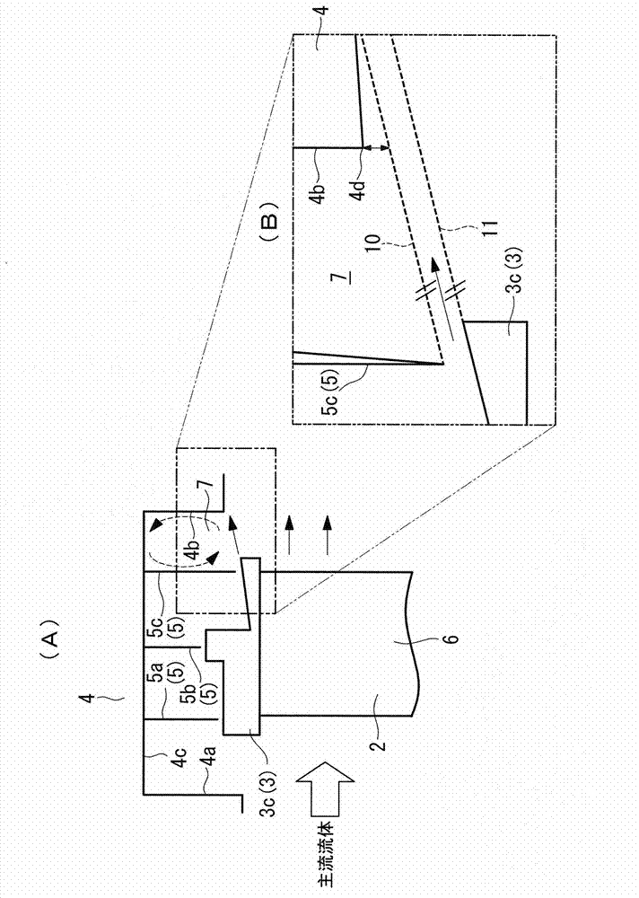
[0075] figure 2 It is the seal structure of the gas turbine in the power generation facility concerning 2nd Embodiment of this invention, (A) shows the schematic stru...


PUM


Abstract

Provided is a seal structure with which it is possible to curtail disturbances to a main fluid stream due to leaked fluid. The seal structure is provided with: shroud members (3a) provided at the tips of a plurality of blades (2) subjected to the main fluid stream, in a manner such that adjacent shroud members come into contact to form a cylinder; a sealing means (5c) connected to a structure (4) provided opposite the shroud members (3a); and a cavity (7), which communicates with the main fluid stream that acts on the blades (2), and comprises a wall section (4b) on the downstream side of the structure (4), the downstream side of the sealing means (5c), and the downstream side of the shroud members (3a). Therein, the end section (4d) of the wall section (4b) on the downstream side of the structure (4) is set apart from a shroud extension line (11), which extends from the downstream side of the shroud (3a), and a sealing means extension line (10), which extends from the downstream side of the sealing means (5c), and is approximately parallel to the shroud extension line (11) with a prescribed gap therebetween, at a position on the opposite side of the shroud extension line (11) when viewed from the sealing means extension line (10).

Description

technical field [0001] The present invention relates to a sealing structure, a turbine equipped with the sealing structure, and a power generating equipment equipped with the turbine, and particularly relates to a sealing structure related to fluid leaking from between a sealing unit and a shroud at the front end of a blade, and a turbine equipped with the sealing structure. A turbine, and power generation equipment including the turbine. Background technique [0002] Generally speaking, if Figure 5 As shown, a rotor blade shroud 53 is provided at each front end of a plurality of rotor blades 51 of the turbine so as to face the turbine casing 52 . The rotor blade shrouds 53 are formed in an annular shape so that adjacent rotor blade shrouds 53 are in contact with each other during the rotation of the aforementioned rotor blades 51 . Between the rotor blade shroud 53 and the turbine housing 52 , a seal portion for connecting a seal fin 54 to the turbine housing 52 side is p...

Claims


Application Information

Patent Timeline
Patent Type & Authority Applications(China)
IPC IPC(8): F01D11/02F01D25/00F01D25/24F02C7/28
CPCF01D11/005F01D5/143F01D11/02F01D5/225F01D11/08F01D25/24F02C7/28F01D25/00
Inventor 桑村祥弘松本和幸大山宏治田中良典松尾朝春
Owner MITSUBISHI POWER LTD
Learn More