Rotary drum underflow pump flow-limiting plate

A technology of restricting plate and underflow pump, applied in the field of restricting plate of rotary drum underflow pump, can solve the problems of intolerance to erosion, waste of materials, time-consuming and labor-intensive, etc., and achieve the effect of prolonging service life and saving maintenance time.

Inactive Publication Date: 2012-12-19
NANJING MEISHAN METALLURGY DEV +1
View PDF2 Cites 0 Cited by
  • Summary
  • Abstract
  • Description
  • Claims
  • Application Information

AI Technical Summary

Problems solved by technology

The gaskets currently used in production have poor wear resistance and are not resistant to erosion, so the gaskets are extremely damaged and cannot meet the requirements at the restrictor plate, and once leakage occurs, they must be replaced in time
If the leakage time reaches 10 minutes, the stainless steel flange will be flushed with a gap, which needs to be dismantled, welded, polished, and installed. When replacing, it is time-consuming, laborious, endless, and wastes materials.

Method used


Image

  • Rotary drum underflow pump flow-limiting plate
  • Rotary drum underflow pump flow-limiting plate

Examples


Embodiment 1

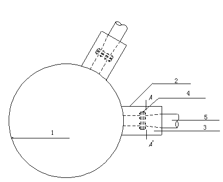
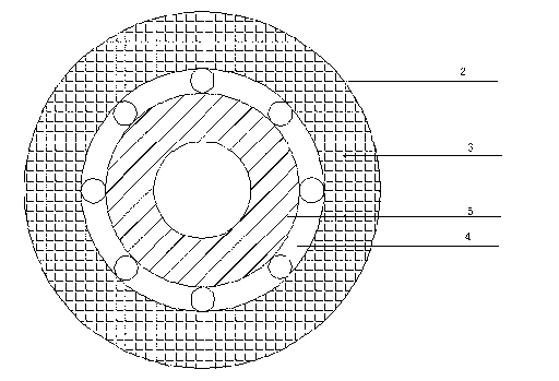
[0015] Replace the gasket at 4 of the flange restrictor plate to ensure that the quick-drying and quick-acting concrete will not be worn through before it solidifies. The upper and lower parts of the sealed chamber 2 with an inner diameter of 450 mm are respectively made of steel plates with a length of 600 mm and a thickness of 10 mm, and then the upper and lower parts are placed on the restrictor plate 4 to form a sealed chamber 2 covering the restrictor plate 4, and the One end of the sealed cavity 4 is welded on the blowing box 1, and the other end is closed and welded with a circular steel plate with a thickness of 10 mm and φ450*165 mm, and is centered on the delivery pipe 5. A pouring hole of φ100mm is opened in the middle of the sealed cavity 2, and concrete is poured into the pouring hole, and tamped with a vibrating rod to form a concrete layer 3, and its structure is as follows figure 1 with figure 2 shown. Since the conveying pipeline 5 is a difficult-to-weld st...


PUM


Abstract

The invention relates to a supporting device of a water slag blowing tower in iron and steel smelting, and especially a device of a flow-limiting plate used when the water slag is fed back to a flushing tank. In order to ensure the tightness of the flow-limiting plate and to prevent leakage under the environment with high erosion and high corrosion, according to the invention, a sealing chamber is added on a basis of an original rotary drum underflow pump flow-limiting plate. One end of the sealing chamber is welded to a blowing tank. The other end of the sealing chamber is annular, and forms a sealed space with the outer wall of a transmission pipeline. The flow-limiting plate is positioned in the sealing chamber. Concrete is filled between the flow-limiting plate and the sealing chamber. With the structure, the service life of the flow-limiting plate is greatly prolonged; maintenance and replacing costs of sealing rings and sealing gaskets are saved; and maintenance time spent by manual reparation of a flow-limiting plate flange is saved.

Description

[0001] technical field [0002] The invention relates to a matching equipment of a water slag blowing tower in iron and steel smelting, in particular to a flow limiting plate used for feeding back water slag into a punching box. [0003] Background technique [0004] The underflow pump is located in the reservoir below the drum. Its function is to feed back the water slag that falls into the reservoir during drying and dehydration in the drum and feed it back into the brewing tank. Therefore, the underflow pump contains more water. scum. At present, water slag is cooled and granulated by circulating water technology. All its conveying pipes are made of stainless steel containing rare earth and other components. The inner wall is cast with wear-resistant materials to resist the erosion of water slag. The underflow pump will contain high concentration In order to ensure the pressure of the water slag entering the blowing tower, a restrictor plate is installed at the front en...

Claims


Application Information

Patent Timeline
Patent Type & Authority Applications(China)
IPC IPC(8): C21B3/06
CPCY02W30/50
Inventor 管德俊高勇
Owner NANJING MEISHAN METALLURGY DEV
Why Eureka
Try Eureka