Backstop gangue beam suspension swinging beam type gangue filing hydraulic support frame with side protection plate

A technology of hydraulic supports and side guards, which is applied to mine roof supports, fillings, mining equipment, etc., and can solve the problem of gangue and other sundries entering the supports, etc.

Active Publication Date: 2012-12-19
CATERPILLAR ZHENGZHOU
View PDF6 Cites 6 Cited by
  • Summary
  • Abstract
  • Description
  • Claims
  • Application Information

AI Technical Summary

Problems solved by technology

[0003] Aiming at the deficiencies in the prior art, the technical problem to be solved by the present invention is to provide a backstop gangue beam hanging swing beam type gangue-filled hydraulic support with side guards to solve the problem of gangue and other sundries entering the front of the support

Method used


Image

  • Backstop gangue beam suspension swinging beam type gangue filing hydraulic support frame with side protection plate
  • Backstop gangue beam suspension swinging beam type gangue filing hydraulic support frame with side protection plate

Examples


Embodiment 1

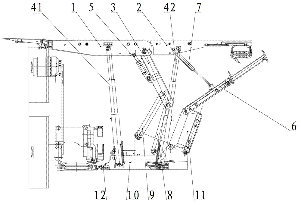
[0021] Such as figure 1 As shown, the embodiment of the present invention provides a rear gangue beam suspension swing beam type gangue filled hydraulic support with side guards, including a front top beam 1, a rear top beam 2 hinged with one end of the front top beam, a front top beam Column 41, rear column 42, upper connecting rod 3, front connecting rod 9, rear connecting rod 8, base 10, pushing frame and pushing jack 12; where upper connecting rod 3 is hinged at the joint between front top beam 1 and rear top beam 2 A three-point-in-one structure is formed on the point to support the cover type bracket, and the upper link 3 is respectively hinged with one end of the front link 9 and the rear link 8, and the other end of the front link 9 and the rear link 8 is respectively connected with the base 10. Hinged; the two ends of the front column 41 are respectively hinged with the front top beam 1 and the front end of the base 10, and the two ends of the rear column 42 are respe...

Embodiment 2

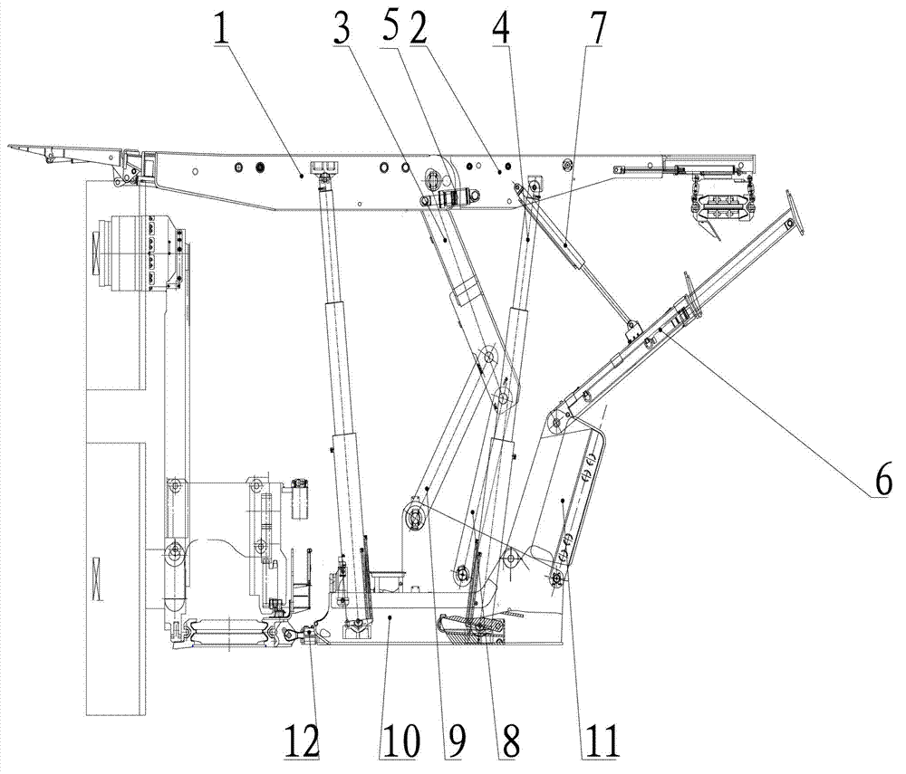
[0026] The difference from Example 1 is that, as figure 2 As shown, the balance jack 5 is arranged between the front top beam 1 and the rear top beam 2 . Other than that, other components and connection methods are the same as those in Embodiment 1, and will not be repeated in this embodiment.

[0027] The working principle of the embodiment of the present invention is as follows:

[0028] The support part of the hydraulic support in the embodiment of the present invention is the same as the support function of the traditional hydraulic support, and the realization process in the filling part is as follows: the pallet on which the filling conveyor is suspended slides in the chute of the rear top beam under the action of the pallet jack To the goaf that needs to be filled, the filling conveyor transports the filler to fill the goaf; the telescopic swing beam hinged on the rear retaining beam with side guards is pushed and pulled by the swing beam jack hinged on the rear top b...


PUM


Abstract

The invention relates to underground comprehensive mechanized coal mining work surface support equipment for a coal mine, in particular to a backstop gangue beam suspension swinging beam type gangue filing hydraulic support frame with a side protection plate for goaf filling. The hydraulic support frame comprises a front top beam, a back top beam, a front upright post, a back upright post, an upper connecting rod, a front connecting rod, a back connecting rod and a base, wherein the back top beam is hinged with one end of the front top beam, a backstop gangue beam with a side protection plate is also hinged on the back end of the base, a telescopic swinging beam is hinged on the backstop gangue beam with the side protection plate, the telescopic swinging beam is suspended in the air through a swinging beam jack, in addition, the angle is adjusted, and the side protection plate of the backstop gangue beam with the side protection plate can be opened to two sides or the single side through the lateral pushing of the jack or other external force during the support frame filling, so a sealed separation plate is formed between the support frames, and sundries such as gangue and the like are prevented from entering the front side of the support frames.

Description

technical field [0001] The invention relates to support equipment for comprehensive mechanized coal mining working faces in underground coal mines, in particular to a backstop gangue beam suspension swing beam type gangue filling hydraulic support with side guard plates for goaf filling. Background technique [0002] my country is rich in coal resources, fully mechanized mining equipment is mature, and coal mining technology is becoming more and more perfect. With the shortage of energy, the pace of coal mining in my country is accelerating, and more and more mines are facing the problem of resource depletion. The problem is that my country has liberated the "three-down" coal pressing by adopting traditional strip mining, relocating villages, filling mining and other technical measures to improve the coal recovery rate. However, with the increase of mining depth, the increase of village relocation costs and the improvement of filling technology, filling mining technology has ...

Claims


Application Information

Patent Timeline
Patent Type & Authority Applications(China)
IPC IPC(8): E21D23/03E21D23/04E21F15/00
Inventor 贾洪现史磊秦树振韩山岭马玉贤谢战洪梁鹤邵俊营杨永福陈素芳肖正宏宋聪惠
Owner CATERPILLAR ZHENGZHOU
Why Eureka
Try Eureka