A machine tool tool support mechanism

A technology of support mechanism and tool, applied in the direction of support, manufacturing tools, metal processing machinery parts, etc., can solve the problems affecting the machining accuracy of the tool, affecting the machining accuracy of the workpiece, and the deflection and deformation of the tool, and achieves convenient operation, good support effect, Reasonable support position

Active Publication Date: 2016-01-27
HANGZHOU BRANCH ZHEJIANG GEELY AUTOMOBILE RES INST +2
View PDF10 Cites 2 Cited by
  • Summary
  • Abstract
  • Description
  • Claims
  • Application Information

AI Technical Summary

Problems solved by technology

During workpiece processing, especially when the machine tool is changing the workpiece or the machine tool is stopped and the tool is returned to its original position during the machining process, due to the long overhang of the tool outside the spindle and the heavy weight of the tool, it takes a long time The tool suspension will cause the tool to deflect and deform under the influence of its own gravity, which will affect the machining accuracy of the subsequent workpiece
[0003] To solve the problem of deflection and deformation of the tool due to long-term suspension, which affects the machining accuracy of the tool, it is necessary to design a corresponding mechanism for supporting the tool when the machine tool is in the above state

Method used


Image

  • A machine tool tool support mechanism
  • A machine tool tool support mechanism
  • A machine tool tool support mechanism

Examples


Embodiment Construction

[0040] In order to make the purpose, technical solutions and advantages of the embodiments of the present invention more clear, specific embodiments will be described in detail below with reference to the accompanying drawings.

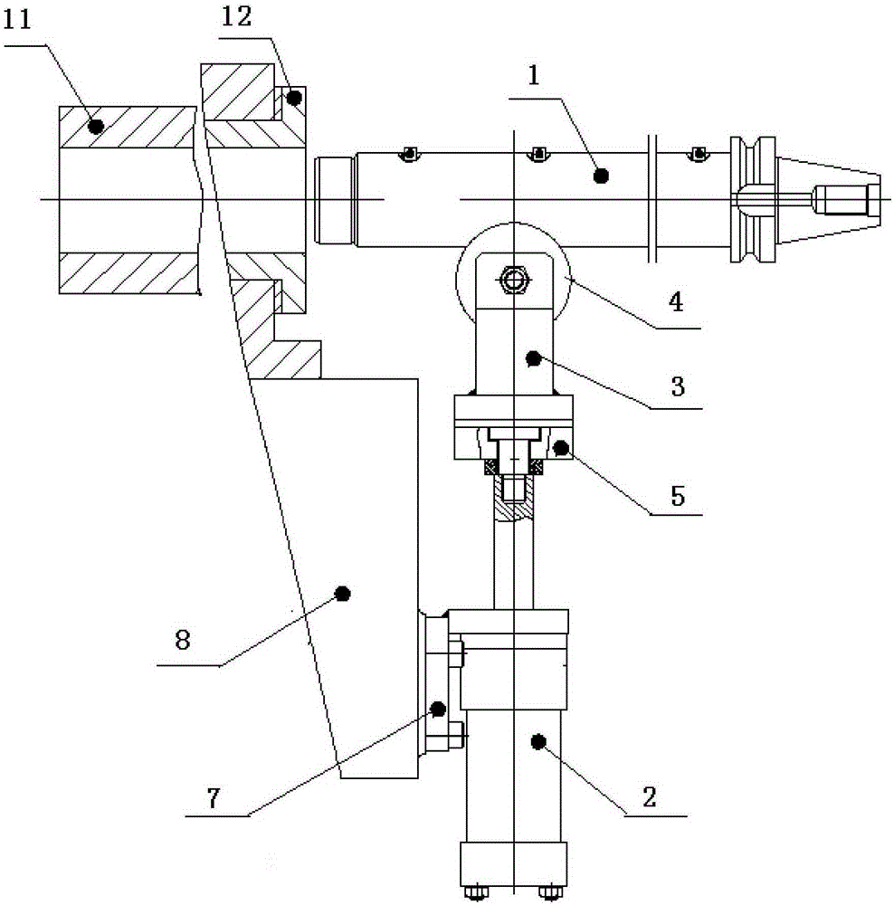
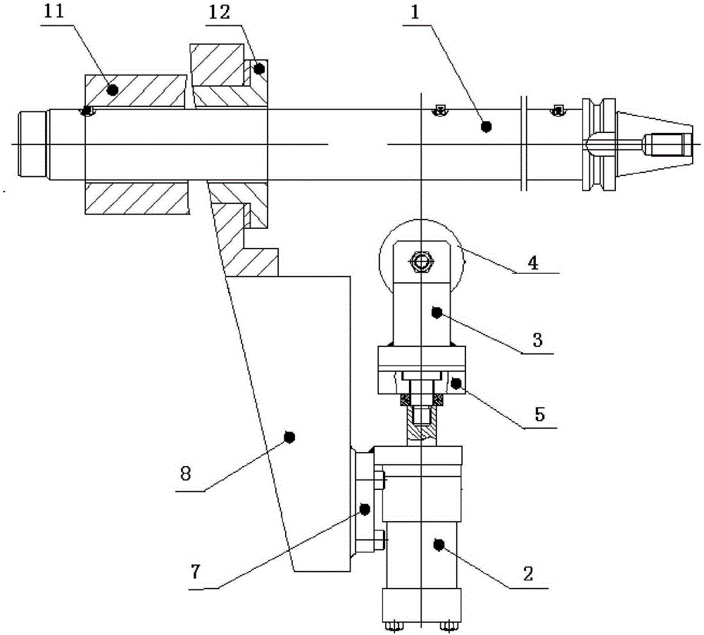
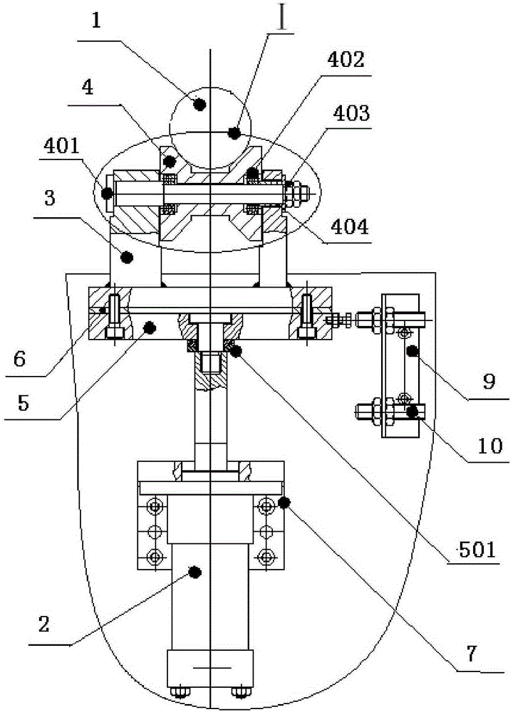
[0041] Such as Figure 1-Figure 10c It is a schematic diagram of an embodiment of the present invention. The embodiment of the present invention provides a tool support mechanism of a machine tool. The support mechanism includes a movable base, which is arranged on the bottom side of the tool 1 and performs telescopic movement toward the tool 1 . The support mechanism also includes a support member, which is arranged on the movable base near the end of the tool 1 . When the movable base is extended to the highest position, the support supports the tool 1 on the horizontal axis.

[0042] The present invention drives the supporting member connected to it to move through the telescopic movement of the movable base, which can make the supporting member c...


PUM


Abstract

The invention discloses a supporting mechanism for a machine tool cutter and relates to the field of machine tool machining. The supporting mechanism comprises a movable base and a supporting part, wherein the movable base is arranged on the bottom side of the cutter and makes flexible motion towards the cutter, and the supporting part is arranged on the movable base; and particularly in the period of reloading a workpiece or in the machine tool stopping period and the cutter returns to a normal position in the machining process, the movable base is extended out to reach the highest position, the cutter is supported on a horizontal axis by the supporting part, and thus the problem that the machining accuracy of the cutter is affected due to the deflection deformation caused by the long-time suspension of the cutter is avoided.

Description

technical field [0001] The invention relates to the field of machine tool processing, in particular to a machine tool tool support mechanism. Background technique [0002] During the processing of parts, holes with large diameter and deep processing depth often appear, such as the processing of the crankshaft hole of the engine block, the processing of the camshaft hole of the cylinder head, etc., so the length of the required processing tool is also corresponding It's longer. During workpiece processing, especially when the machine tool is changing the workpiece or the machine tool is stopped, and the tool is returned to its original position during the machining process, due to the long overhang of the tool outside the spindle and the heavy weight of the tool, it takes a long time The tool suspension will cause the tool to deflect and deform under the influence of its own gravity, which will affect the machining accuracy of the subsequent workpiece. [0003] To solve the...

Claims


Application Information

Patent Timeline
Patent Type & Authority Patents(China)
IPC IPC(8): B23Q3/00
Inventor 童向荣王振陈启云李慧军由毅赵福全
Owner HANGZHOU BRANCH ZHEJIANG GEELY AUTOMOBILE RES INST
Why Eureka
Try Eureka