A method for calibrating the axis distance of a drilling and gong dual-purpose machine

A technology for calibrating shafts and machines, applied in the mechanical field, can solve problems such as affecting machining accuracy, and achieve the effects of improving machining performance, simple calibration steps, and solving machining accuracy problems

Active Publication Date: 2020-02-28
HANS CNC SCI & TECH
View PDF7 Cites 0 Cited by
  • Summary
  • Abstract
  • Description
  • Claims
  • Application Information

AI Technical Summary

Problems solved by technology

Due to the thermal expansion of the mechanical structure and the workpiece, the distance between the two axes will definitely change after a period of time. If it is not adjusted in time, it will affect the machining accuracy.

Method used


Image

  • A method for calibrating the axis distance of a drilling and gong dual-purpose machine
  • A method for calibrating the axis distance of a drilling and gong dual-purpose machine
  • A method for calibrating the axis distance of a drilling and gong dual-purpose machine

Examples


Embodiment Construction

[0016] In order to make the object, technical solution and advantages of the present invention clearer, the present invention will be further described in detail below in conjunction with the accompanying drawings and embodiments. It should be understood that the specific embodiments described here are only used to explain the present invention, not to limit the present invention.

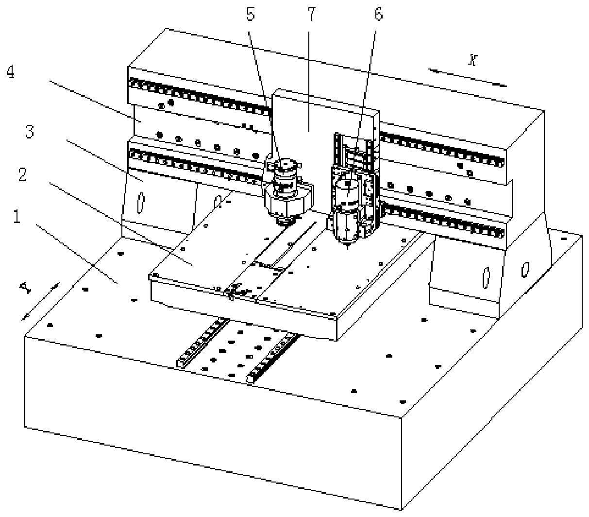
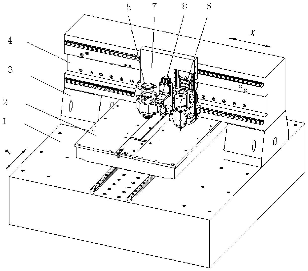
[0017] figure 2 Shows a schematic structural view of a drilling and gong dual-purpose machine according to an embodiment of the present invention, including a bed 1, a beam 4 arranged on the bed, a workbench 2, and a drill shaft 5 and a gong shaft 6 located on a bottom plate 7, and the bottom plate 7 is installed on the beam 4 and moves horizontally along the beam 4, the workbench 2 is installed on the bed 1 and moves horizontally along the bed 1, and the direction of movement of the bottom plate 7 and the workbench 2 is vertical. The circuit board to be processed is placed on the workbench 2 and...


PUM


Abstract

The invention relates to the field of machinery, in particular to a drilling and milling dual-purpose machine and a method for calibrating distances between shafts of the drilling and milling dual-purpose machine. The drilling and milling dual-purpose machine comprises a bed body, a beam arranged on the bed body, a work bench, a drilling shaft, a milling shaft and a vision system, wherein the drilling shaft and the milling shaft are located on a bottom plate; and the vision system is located on the bottom plate. The method for calibrating the distances between the shafts of the drilling and milling dual-purpose machine comprises the following steps of (a) drilling holes on a circuit board by adopting the drilling shaft and the milling shaft of the drilling and milling dual-purpose machine respectively; (b) locating the two holes by using the vision system to obtain machine coordinates of the two holes; and (c) calculating the distances between physical positions, in X and Y coordinate directions, of the milling shaft and the drilling shaft, namely the distances between the two shafts according to machine coordinate values of the two holes. According to the method for calibrating the distances between the shafts, the problem of machining precision caused by deformation due to thermal expansion of a mechanical structure and a workpiece is solved and the machining property of equipment is improved.

Description

technical field [0001] The invention relates to the mechanical field, in particular to a method for calibrating the distance between axes of a drilling and gong dual-purpose machine. Background technique [0002] Since circuit board manufacturers need proofing, proofing requires the use of drilling rigs and gong machines for drilling and forming respectively. In order to save time for proofing, a dual-purpose drilling and gong machine that can complete drilling and forming on the same machine came into being. The use of drilling and gong dual-purpose machines for proofing can not only reduce the time for panel installation, disassembly and repositioning, but also save equipment investment. In addition, as the volume of electronic products becomes smaller and smaller, and the circuit board develops in the direction of lightness, thinness, and smallness, the processing precision of the circuit is required to be higher and higher. Due to the complexity of the PCB board materi...

Claims


Application Information

Patent Timeline
Patent Type & Authority Patents(China)
IPC IPC(8): H05K3/00B23P23/02
CPCB23P23/02H05K3/00H05K3/0044
Inventor 蔡小丽翟学涛杨朝辉高云峰
Owner HANS CNC SCI & TECH
Why Eureka
Try Eureka