Waste tire slitting device

A waste tire and strip cutting technology, which is applied in the direction of smoke removal, dispersed particle filtration, cleaning methods and utensils, etc., can solve the problems of excessive heat generation, easy generation of dust cutting knives, etc., to improve the safety factor, shorten the time of intermediate transfer, The effect of avoiding environmental pollution

Inactive Publication Date: 2019-02-01
重庆九橡化大橡胶科技有限责任公司
View PDF3 Cites 2 Cited by
  • Summary
  • Abstract
  • Description
  • Claims
  • Application Information

AI Technical Summary

Problems solved by technology

[0005] The purpose of the present invention is to provide a waste tire strip cutting equipment to solve the problems of easy generation of dust and excessive heating of the cutter during the cutting process of the tire strip cutting equipment in the prior art

Method used


Image

  • Waste tire slitting device
  • Waste tire slitting device
  • Waste tire slitting device

Examples


Embodiment Construction

[0026] The following is further described in detail through specific implementation methods:

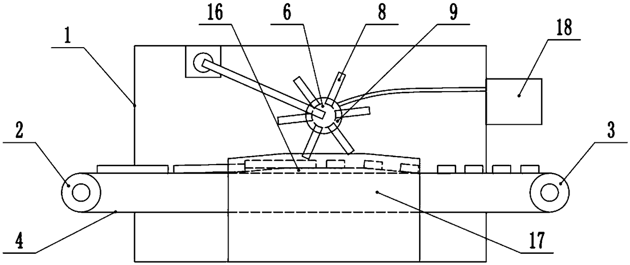
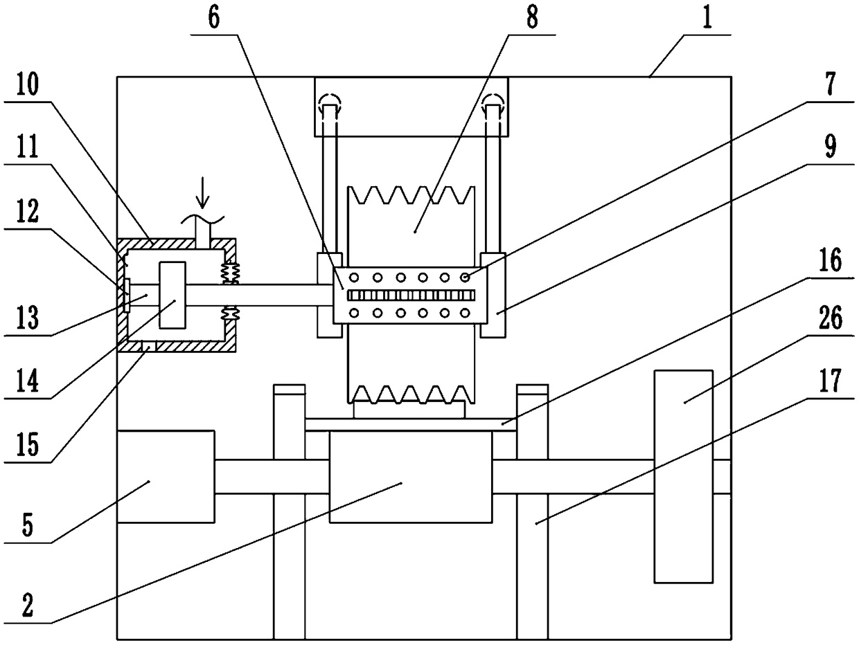
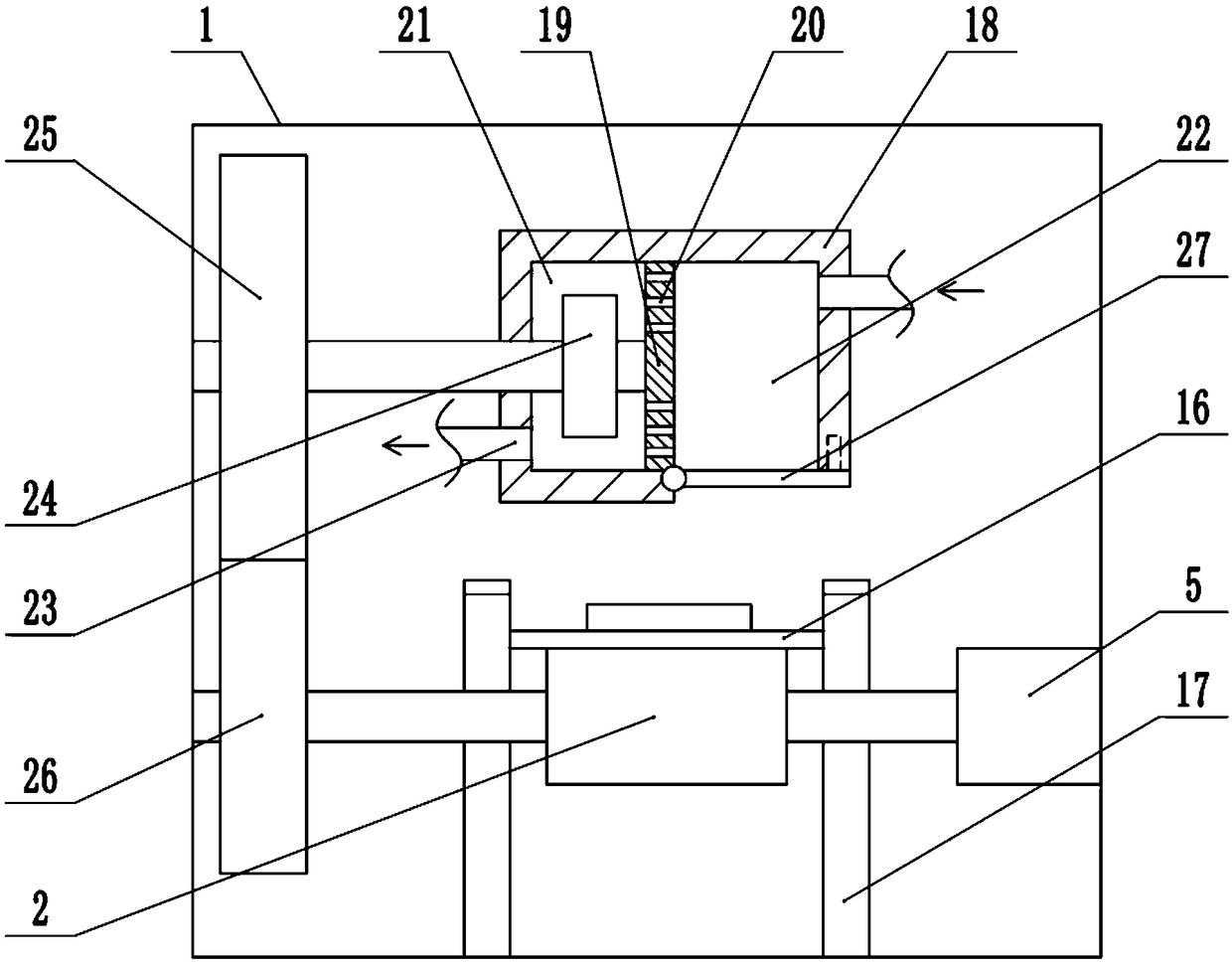
[0027] The reference signs in the drawings of the description include: frame 1, driving wheel 2, driven wheel 3, conveyor belt 4, motor 5, first rotating shaft 6, through hole 7, cutter 8, support block 9, air guide box 10, slide Slot 11, slider 12, second shaft 13, turbine 14, second air outlet 15, horizontal plate 16, vertical plate 17, dust box 18, partition 19, filter hole 20, first chamber 21, second The chamber 22 , the first air outlet hole 23 , the negative pressure vane 24 , the first gear 25 , the second gear 26 , and the baffle 27 .

[0028] The embodiment is basically as attached Figure 1 to Figure 4 Shown:

[0029] The scrap tire cutting equipment includes a frame 1, on which a transmission unit, a cutting unit and a dust removal unit are arranged. The transmission unit comprises a driving wheel 2, a driven wheel 3 and a conveyor belt 4 wound between the driving whee...


PUM


Abstract

The invention relates to the technical field of tire processing, and discloses a waste tire slitting device. The waste tire slitting device comprises a rack, and a conveying unit, a cutting unit and adust removing unit are arranged on the rack, wherein the conveying unit comprises a driving wheel and a conveyer belt; the cutting unit comprises a hollow first rotating shaft and a driving mechanism; through holes are formed in the first rotating shaft; a cutter is fixedly connected to the first rotating shaft; hollow supporting blocks are arranged on the rack; the first rotating shaft is rotatably connected to the supporting blocks and communicates with the supporting blocks; the dust removing unit comprises a dust collection box; a partition is fixedly connected in the dust collection box;filter holes used for filtering flying dust are formed in the partition; the partition divides the dust collection box into a first cavity and a second cavity; a first air outlet is formed in the first cavity; the second cavity communicates with the supporting blocks; a negative pressure blade is rotatably connected in the first cavity; the negative pressure blade is coaxially connected with a first gear; and a second gear which meshes with the first gear is coaxially connected to the driving wheel. According to the waste tire slitting device, flying dust can be collected and the cutter can be cooled during cutting.

Description

technical field [0001] The invention relates to the technical field of tire processing, in particular to a strip cutting equipment for waste tires. Background technique [0002] To recycle and reuse waste tires, the waste tires are first decomposed and then pulverized. An important step in the disassembly process is to cut the tires into strips. Traditional tire strip cutting equipment needs to manually hold the tires for operation, which is inconvenient to operate, labor-intensive, dangerous, low work efficiency, and the dimensional accuracy of the strips. It is relatively low, and it is not convenient to sharpen the tool. [0003] In order to solve the above problems, Chinese patent (CN205969198U) discloses a tire strip cutting device, which includes a workbench and a strip cutter; The plate rotates vertically to the first rotating shaft; an angle adjustment device is provided between the fixed plate and the supporting plate; a lifting device is provided at the bottom of...

Claims


Application Information

Patent Timeline
Patent Type & Authority Applications(China)
IPC IPC(8): B29B17/00B08B15/00B01D46/10
CPCB01D46/10B08B15/007B29B17/00B29B2017/0021Y02W30/62
Inventor 董大伟全永胜田宗军
Owner 重庆九橡化大橡胶科技有限责任公司
Why Eureka
Try Eureka