Heat exchange device and air conditioner

A technology for heat exchange devices and air conditioners, which is applied to indirect heat exchangers, heat exchanger shells, heat exchanger types, etc. Thermal effects, volume reduction, effects of reducing the number of layouts

Inactive Publication Date: 2020-11-03
GD MIDEA HEATING & VENTILATING EQUIP CO LTD +1
View PDF8 Cites 1 Cited by
  • Summary
  • Abstract
  • Description
  • Claims
  • Application Information

AI Technical Summary

Problems solved by technology

[0002] The gas ignited by the burner can flow into the heat exchange tube for heat exchange. In order to increase the heat exchange area of ​​the heat exchange tube, it is usually necessary to increase the length of the heat exchange tube, and the volume of the heat exchange tube increases, resulting in an increase in the volume of the air conditioner.

Method used


Image

  • Heat exchange device and air conditioner
  • Heat exchange device and air conditioner
  • Heat exchange device and air conditioner

Examples


Embodiment 1

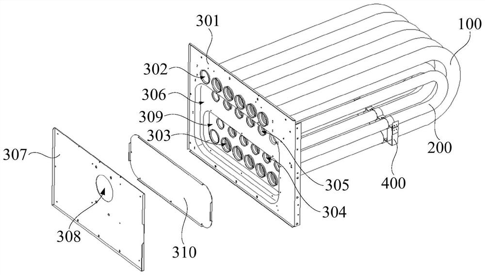
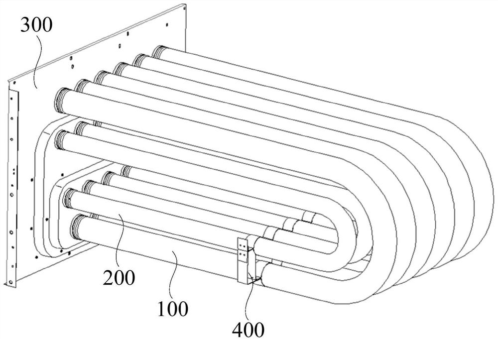
[0059] combine figure 1 and figure 2 As shown, the embodiment of the first aspect of the present invention proposes a heat exchange device, including: a first heat exchange tube 100 and a second heat exchange tube 200, the first end of the first heat exchange tube 100 communicates with the outside world, the second The second heat exchange tube 200 is located in the surrounding area of ​​the first heat exchange tube 100, the first end of the second heat exchange tube 200 communicates with the second end of the first heat exchange tube 100, and the second end of the second heat exchange tube 200 Connect with the outside world.

[0060] The first end of the first heat exchange tube 100 communicates with the outside world, that is, the external air can flow into the first heat exchange tube 100 through the first end of the first heat exchange tube 100 or the gas can pass through the first end of the first heat exchange tube 100 The first end exits the first heat exchange tube ...

Embodiment 2

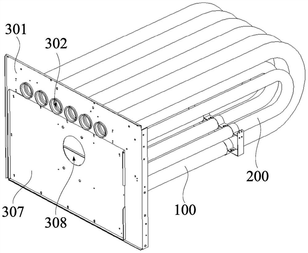
[0067] combine figure 2 and image 3 As shown, in the above embodiments, the first end of the first heat exchange tube 100 is used to connect with the air supply device 500 .

[0068] In this embodiment, the first end of the first heat exchange tube 100 is specifically defined as the intake end, the gas supply device 500 can provide gas, and the gas supply device 500 is connected to the first end of the first heat exchange tube 100, The ignited gas can flow into the first heat exchange tube 100 through the first end of the first heat exchange tube 100, the gas flows in the first heat exchange tube 100, and passes through the second end of the first heat exchange tube 100 and the second end of the first heat exchange tube 100. The first end of the second heat exchange tube 200 flows into the second heat exchange tube 200 , and the gas that has undergone heat exchange is discharged and collected through the second end of the second heat exchange tube 200 .

[0069] Since the ...

Embodiment 3

[0074] combine figure 1 , figure 2 and image 3 As shown, in the above embodiment, the heat exchange device further includes a fixing plate 300 on which the first heat exchange tube 100 and the second heat exchange tube 200 are disposed.

[0075] In this embodiment, the first heat exchange tube 100 and the second heat exchange tube 200 can be installed on the fixing plate 300 . Specifically, the first end of the first heat exchange tube 100, the second end of the first heat exchange tube 100, the first end of the second heat exchange tube 200, and the second end of the second heat exchange tube 200 are all connected to a fixed On the plate 300 , the fixing plate 300 can support and fix the end of the first heat exchange tube 100 and the end of the second heat exchange tube 200 , avoiding the end of the first heat exchange tube 100 and the second heat exchange tube 200 Shaking occurs at the end to ensure the stability of intake and exhaust.

[0076] The air conditioner als...


PUM


Abstract

The invention provides a heat exchange device and an air conditioner. The heat exchange device comprises a first heat exchange pipe and a second heat exchange pipe; the first end of the first heat exchange pipe communicates with the outside; the second heat exchange pipe is located in a surrounding area of the first heat exchange pipe, the first end of the second heat exchange pipe communicates with the second end of the first heat exchange pipe, and the second end of the second heat exchange pipe communicates with the outside; due to the fact that the second heat exchange pipe is located in the surrounding area of the first heat exchange pipe, the second heat exchange pipe does not extend out of the outer side of the outer edge of the first heat exchange pipe, the size of the heat exchange device is not changed on the basis of increasing the heat exchange area, a larger installation space does not need to be provided for the heat exchange device, the situation that the size of the airconditioner with the heat exchange device is large is avoided, and therefore the heat exchange effect of the heat exchange device is effectively improved on the basis that the size of the heat exchange device is not changed.

Description

technical field [0001] The invention belongs to the technical field of air conditioners, and in particular relates to a heat exchange device and an air conditioner. Background technique [0002] The gas ignited by the burner can flow into the heat exchange tube for heat exchange. In order to increase the heat exchange area of ​​the heat exchange tube, it is usually necessary to increase the length of the heat exchange tube, and the volume of the heat exchange tube increases, resulting in an increase in the volume of the air conditioner. . Contents of the invention [0003] The present invention aims to solve one of the technical problems existing in the prior art or related art. [0004] In view of this, the first aspect of the present invention proposes a heat exchange device, comprising: a first heat exchange tube, the first end of which communicates with the outside world; a second heat exchange tube, located at In the surrounding area of ​​the first heat exchange tub...

Claims


Application Information

Patent Timeline
Patent Type & Authority Applications(China)
IPC IPC(8): F24F13/30F28D7/06F28F9/013F28F9/02
CPCF24F13/30F28D7/06F28F9/013F28F9/02
Inventor 程张良李世泽
Owner GD MIDEA HEATING & VENTILATING EQUIP CO LTD
Why Eureka
Try Eureka