Electromagnetic directional valve

An electromagnetic reversing valve and electromagnet technology, which is applied in fluid pressure actuators, servo motor components, mechanical equipment, etc., can solve the problem of miniaturization of electromagnetic reversing valves, reversing sensitivity and energy consumption that cannot meet actual requirements, etc. problems, to achieve the effects of miniaturization design, reduced reaction force, and shortened working stroke

Inactive Publication Date: 2012-12-19
NINGBO ZHENHAI HUALI HYDRAULIC ELECTROMECHANICAL CO LTD
View PDF8 Cites 5 Cited by
  • Summary
  • Abstract
  • Description
  • Claims
  • Application Information

AI Technical Summary

Problems solved by technology

[0003] Due to the lack of fundamental changes in its technical characteristics, with the development of hydraulic systems, the existing electromagnetic reversing valves are increasingly unable to meet the actual requirements in terms of miniaturization, reversing sensitivity and energy consumption, and need to be studied. and improve

Method used


Image

  • Electromagnetic directional valve
  • Electromagnetic directional valve

Examples


Embodiment Construction

[0020] The present invention will be further described in detail below in conjunction with the accompanying drawings and embodiments.

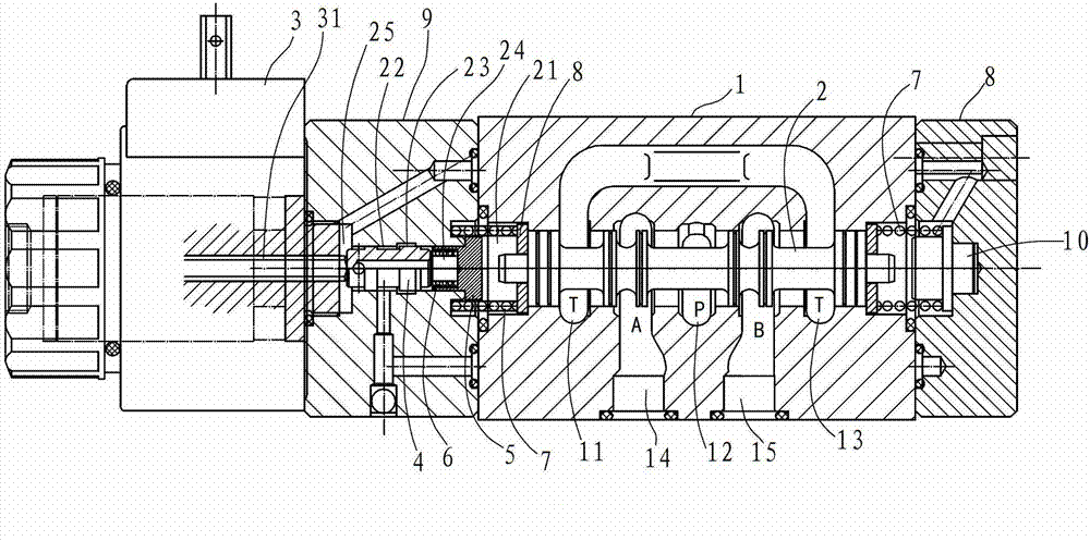
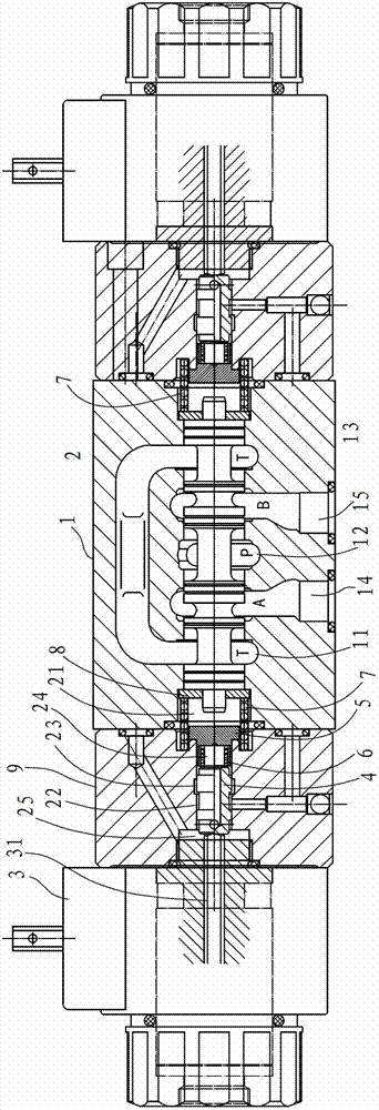
[0021] Such as figure 1 As shown, the electromagnetic reversing valve in this embodiment is a single-control electromagnetic reversing valve, including valve body 1, main valve core 2, electromagnet 3, main return spring 7, side cover 9, pilot spool 4, pilot reset Spring 6 and end cap 8.

[0022] The valve body 1 has an oil inlet chamber 12, an oil return chamber 11, a working chamber 14 and a working chamber 15. The main valve core 2 is located in the valve body 1 and can move back and forth along the axial passage of the valve body to change the reversing direction. The working state of the valve. The middle part of the rear end of the main valve core 2 protrudes axially to form a convex part 21 .

[0023] The main return spring 7 acts on the main spool 2 and moves the main spool 2 to the initial position. There are two main return spring...


PUM


Abstract

The invention discloses an electromagnetic directional valve which comprises a valve body, a main valve core, an electromagnet and a main restoring spring, wherein the main valve core is positioned in the valve body and can move back and force along an axial channel of the valve body. The electromagnetic directional valve is characterized by also comprising a side cover, a pilot valve core and a pilot restoring spring, wherein the side cover is arranged on one side of the valve body; the pilot valve core can move back and force in an axial duct; the electromagnet is arranged on the other side of the side cover; and a push rod of the electromagnet pushes against the pilot valve core. Compared with the prior art, the electromagnetic directional valve provided by the invention has the advantages that with adoption of a hydraulic amplification principle and combination of a pilot control structure, an original working stroke is greatly shortened, and thus the miniaturization design on the electromagnetic directional valve is favorable; and meanwhile, the working stroke is shortened, and thus power can be greatly reduced.

Description

technical field [0001] The invention relates to a reversing valve and belongs to the technical field of hydraulic control components. Background technique [0002] In the mechatronic automatic control hydraulic system, the electromagnetic reversing valve is the most widely used hydraulic component. Most of the products were developed in the 1970s or introduced technology in the 1980s. A common electromagnetic reversing valve is composed of a valve body, a valve core, an electromagnet and a return spring. The valve core is held in the middle position or the initial position by the return spring when there is no power on (except for pulse valves); after power on, the electromagnet The thrust acts on the spool through the push rod and pushes it from the rest position to the working position (end position). The reversing of this type of electromagnetic reversing valve is realized by directly deriving the movement of the valve core by the output force of the electromagnet. It ...

Claims


Application Information

Patent Timeline
Patent Type & Authority Applications(China)
IPC IPC(8): F15B13/02
Inventor 戴高枫刘佳明
Owner NINGBO ZHENHAI HUALI HYDRAULIC ELECTROMECHANICAL CO LTD
Why Eureka
Try Eureka