
Universal compact type forged steel self-sealing stop valve

A self-sealing and compact technology, used in shaft seals, lift valves, valve details, etc., can solve problems such as affecting sealing performance, increasing costs, and increasing product costs.

Inactive Publication Date: 2012-12-19
张丽智
View PDF5 Cites 10 Cited by
  • Summary
  • Abstract
  • Description
  • Claims
  • Application Information

AI Technical Summary

Problems solved by technology

There are two types of connection between the valve body and the bonnet: one is threaded connection between the outer side of the valve body and the upper end of the inner side of the bonnet, and the other is to connect the valve body and the bracket with evenly distributed studs. The volume of the valve body is large, and the appearance of the product is relatively heavy, which increases the cost of the product
The existing forged steel self-sealing globe valve does not have the function of prompting the degree of opening and closing, so that the pipeline workers cannot control the flow well
The valve stem of the existing forged steel self-sealing globe valve mainly rotates and lifts to drive the valve disc. The rotation of the valve stem will cause the valve disc to rub against the sealing surface of the valve body, which will easily cause scratches on the sealing surface and affect its sealing performance, resulting in shortened valve life
Existing forged steel self-sealing gate valves and globe valves have poor compatibility. There are many types of fittings for gate valves, globe valves, and Y-type globe valves of the same caliber, which indirectly increases the cost of the company's warehouse management.

Method used


Image

  • Universal compact type forged steel self-sealing stop valve
  • Universal compact type forged steel self-sealing stop valve
  • Universal compact type forged steel self-sealing stop valve

Examples


Embodiment Construction

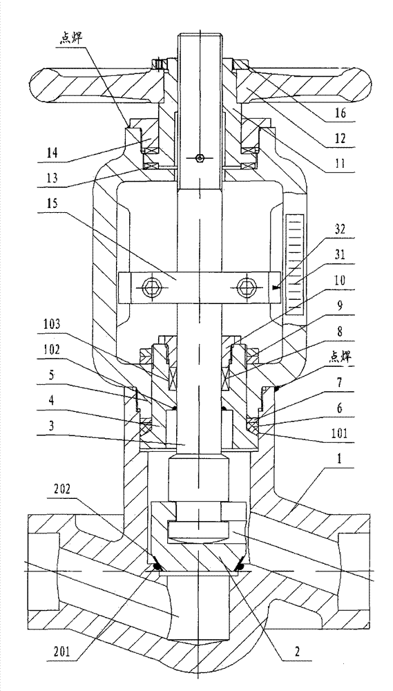
[0012] like figure 1 The universal compact forged steel self-sealing globe valve shown includes valve body 1, valve disc 2, valve stem 3, stuffing box 4, valve cover 5, wedge-shaped sealing ring 6, adjusting pad 7, packing 8, and adjusting nut 9 , Packing gland 10, stem nut 11, hand wheel 12, plane needle roller bearing 13, bracket gland 14, clip row assembly 15, lock nut 16 and other components. The valve disc 2 is fixedly connected with the lower end of the valve stem 3, the upper end of the valve stem 3 passes through the stuffing box 4 and the valve cover 5, and a plane needle bearing 13 is placed on the top and bottom of the valve stem nut 11, and then put into the upper groove of the valve cover 5, and then connected with the The valve stem 11 is connected, and the bracket gland 14 is threadedly connected with the groove of the valve cover 5. The upper end of the valve stem nut 11 is connected with the hand wheel 12. The hand wheel 12 has a lock nut 16 and the upper end ...


PUM


Abstract

The invention provides a universal compact type forged steel self-sealing stop valve, and is characterized by comprising a valve body, a valve cap, a valve clack, a valve stem, a hand wheel, a valve stem nut, a packing box, a clamping and ranking component, and the like, wherein the valve clack is connected with the lower end of the valve stem; the upper end of the valve stem extends out of the valve cap and is connected with the valve stem nut; the valve stem nut is put into a groove in the upper end of the valve cap; a support gland is connected and fixed with the groove in the valve cap through screw threads; the upper end part of the valve stem nut is connected with the hand wheel; the hand wheel is fixedly connected with the valve stem nut through a lock nut; the valve body is connected and fixed with the valve cap through screw threads; the packing box is arranged between the valve body and the valve cap and extends out of the valve cap to be connected and fixed by the lock nut; packing at a packing case is connected and fixed by a packing gland; and three seals are arranged at the packing, that is to say, firstly, a wedge-shaped sealing ring is arranged between the packing box and the valve body, secondly, back sealing functions are fulfilled by the packing box and the valve stem, and thirdly, the packing case is arranged on the packing box.

Description

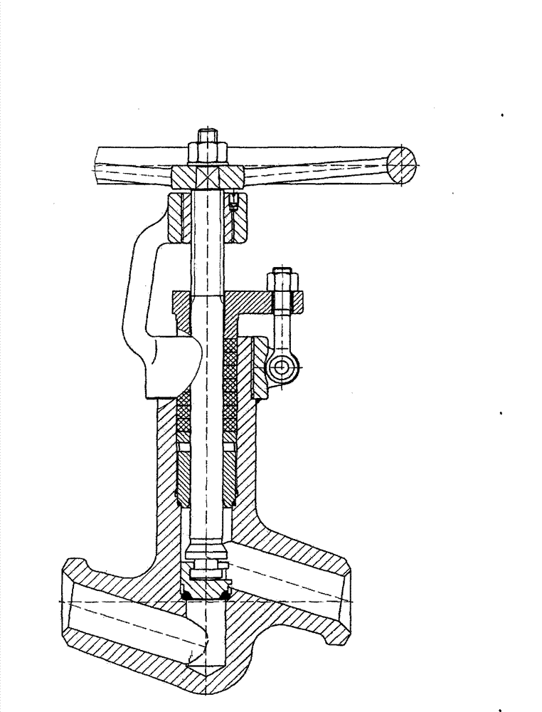
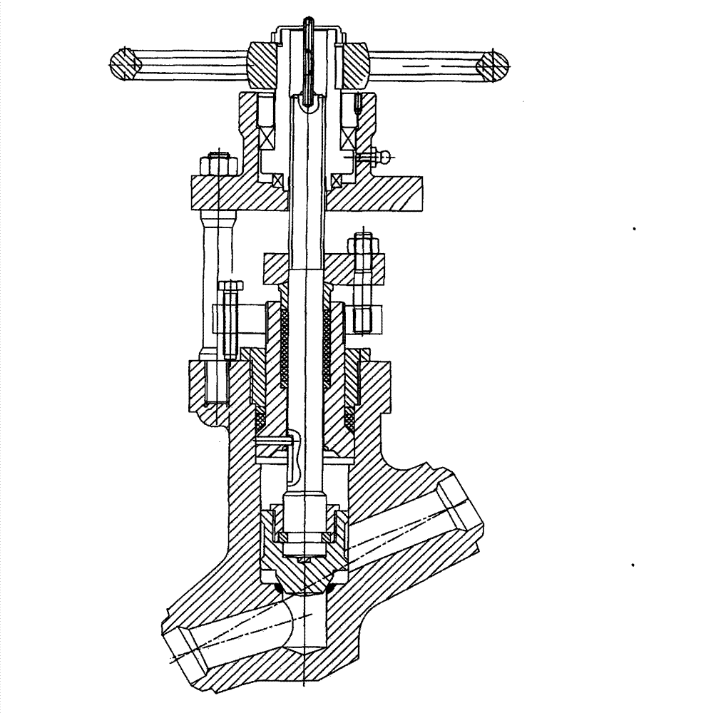
technical field [0001] The invention belongs to the technical field of valves, in particular to a universal compact forged steel self-sealing globe valve. Background technique [0002] Existing forged steel self-sealing stop valve is made up of valve body, bonnet, valve clack, valve stem, hand wheel, valve stem nut, self-sealing pad and adjusting pad etc. There are two types of connection between the valve body and the bonnet: one is threaded connection between the outer side of the valve body and the upper end of the inner side of the bonnet, and the other is to connect the valve body and the bracket with evenly distributed studs. The volume of the valve body is large, and the appearance of the product is relatively heavy, which increases the cost of the product. The packing sealing device is composed of packing and packing pressure plate. The packing pressure plate is pressed on the packing through the swing bolts fixed at both ends of the bracket to realize the sealing h...

Claims


Application Information

Patent Timeline
Patent Type & Authority Applications(China)
IPC IPC(8): F16K1/00F16K41/02F16K27/12F16K27/02
Inventor 张丽智
Owner 张丽智
Learn More