
Duplex pipe for gas draining and hole sealing by grouting

A gas drainage and grouting pipe technology, which is applied in the field of gas drainage pipes and coal mine gas drainage pipes, can solve the problems of inability to guarantee the depth and length of sealing holes, high cost of transfer and labor, and low gas drainage concentration. Achieve the effect of eliminating the loss of waste holes, improving the sealing effect, and simplifying process problems

Inactive Publication Date: 2012-12-19
上海米维矿业科技有限公司 +1
View PDF6 Cites 4 Cited by
  • Summary
  • Abstract
  • Description
  • Claims
  • Application Information

AI Technical Summary

Problems solved by technology

[0004] There are mainly the following methods for sealing the gas drainage hole: 1) Cement slurry sealing: after the cement is consolidated, the shrinkage is relatively large, and the sealing effect is not good; Use a towel dipped in polyurethane grout at both ends to set the plugs, and then bury the grouting pipe for grouting. The gas can only be extracted 48 hours after the construction is completed. The process is complex, the construction period is long, and the cost of lightering and labor is high; 3) Polyurethane foaming Material sealing: no matter manual sealing or grouting machine grouting, since the gap between the gas drainage pipe and the drilled hole is small, usually between 15-20mm, and there are still some residues in the drilled hole, regardless of It is difficult to extend into the depth of the borehole along the gap between the gas drainage pipe and the borehole, whether it is a towel stained with grout or another grouting pipe is installed to seal the hole by the grouting machine, and the sealing depth cannot be guaranteed and length
[0005] Due to the defects and backwardness of the sealing construction technology commonly used in coal mines, the concentration of gas drainage is low and the drainage effect is not ideal

Method used


Image

  • Duplex pipe for gas draining and hole sealing by grouting
  • Duplex pipe for gas draining and hole sealing by grouting
  • Duplex pipe for gas draining and hole sealing by grouting

Examples


Embodiment Construction

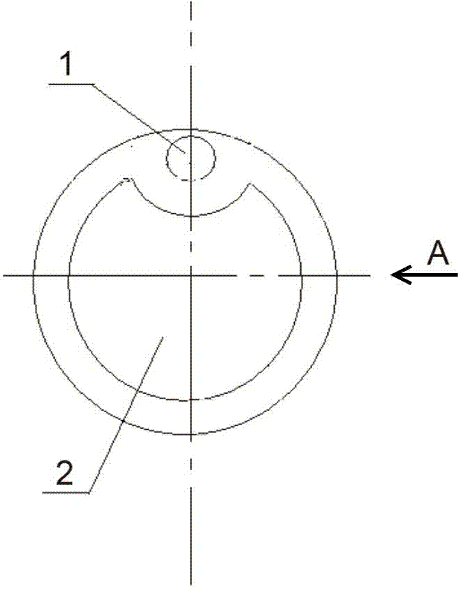
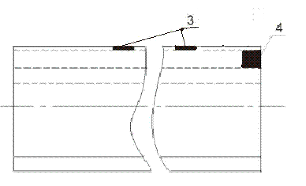
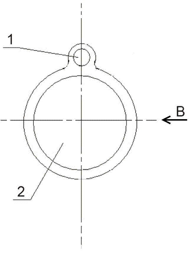
[0021] figure 1 It is one of the structural diagrams of the present invention (the grouting pipe is placed inside the gas drainage pipe), figure 2 for figure 1 A schematic diagram of the structure; image 3 It is the second structural diagram of the present invention (the grouting pipe is placed outside the gas drainage pipe), Figure 4 for image 3 Schematic diagram of the B-direction structure. The figure clearly shows a gas drainage and grouting sealing double pipe of the present invention, including a gas drainage pipe 2 and a grouting pipe 1, characterized in that: the gas drainage pipe 2 and the injection pipe The central axes of the grouting pipes 1 are arranged parallel to each other and in the same direction, and the gas drainage pipe 2 and the grouting pipe 1 are attached to each other and integrated into one body. figure 1 and figure 2 The structure shown is that the inner diameter of the gas drainage pipe 2 is larger than the outer diameter of the grouti...


PUM


Abstract

The invention relates to a gas draining pipe, and in particular to a structure of a duplex pipe for gas draining and hole sealing by grouting, belonging to the technical field of the gas draining pipe for coal mine. The duplex pipe is characterized in that the central axis of the gas draining pipe and the central axis of a grouting pipe are arranged in parallel in the same direction; the gas draining pipe and the grouting pipe are clung to each other and are connected integrally; the duplex pipe is operated by a method as follows: the orifice of the grouting pipe is plugged by a rubber rod at the plugging end of the duplex pipe; one or more grouting holes are drilled in the wall of the grouting pipe; the aperture of the grouting hole is the same as the internal diameter of the grouting pipe; and the other end of the grouting pipe is connected with a quantitative grouting pump, so that grouting liquid enters a gap between the outer side of the draining pipe and the inner wall of a drilled draining hole from the grouting hole of the grouting pipe. The duplex pipe for gas draining and hole sealing by grouting provided by the invention has the beneficial effects that the duplex pipe has a simple structure, can be formed in one step on an extruder, and is convenient to manufacture; and the duplex pipe also has the beneficial effects that the duplex pipe is convenient to operate, the subsequent hole sealing construction process is greatly simplified, and the duplex pipe has good gas tightness.

Description

technical field [0001] The present invention relates to a gas drainage pipe, in particular to a gas drainage and grouting sealing double pipe structure with dual functions of gas drainage and grouting sealing, and a method for using the double pipe. It belongs to the technical field of coal mine gas drainage pipe. Background technique [0002] With the continuous extension of mining depth and the increase of mining intensity in my country's coal mines, the amount of gas emitted from mines has also increased correspondingly, resulting in more serious gas disasters, especially coal and gas outburst disasters, and the safety production situation is still very severe. Gas drainage is the basic means of gas development and utilization, and it is also an important safety measure for high gas mines. Therefore, it is still a very important work in the future to insist on multiple measures to further improve the gas drainage effect. There are many factors that affect the effect of ...

Claims


Application Information

Patent Timeline
Patent Type & Authority Applications(China)
IPC IPC(8): F16L9/19E21F7/00
Inventor 刘向东
Owner 上海米维矿业科技有限公司
Learn More