Anti-freezing device for closed cooling tower

A closed cooling tower and cooling tower technology, applied in the field of cooling tower antifreeze, can solve the problems of complex operation, freezing cracked cooling coils, and reduced heat capacity of circulating water, and achieve convenient operation, prevention of freezing cracks, and reliable work Effect

Inactive Publication Date: 2012-12-19
SHANGHAI KING SUN COOLING EQUIP
View PDF6 Cites 9 Cited by
  • Summary
  • Abstract
  • Description
  • Claims
  • Application Information

AI Technical Summary

Problems solved by technology

[0004] However, it has been proved that the above two solutions have different defects: the defect of the first solution is that adding ethylene glycol will reduce the heat capacity of the circulating water, resulting in a decrease in the heat exchange capacity between the circulating water and the inner wall of the tube, thus affecting the heat transfer effect, and the discharge will cause pollution to the environment
The disadvantage of the second scheme is that the operation is complicated. Due to the complex structure design of the closed cooling tower, it is difficult to discharge all the circulating water in the pipe. Since some circulating water will remain in the pipe, the cooling coil will freeze and crack in winter; moreover, if In winter, the closed cooling tower is not always shut down, that is, the closed cooling tower is intermittently used or stopped. In this way, it is very troublesome to replenish cooling water before each closed cooling tower is operated.

Method used


Image

  • Anti-freezing device for closed cooling tower

Examples


Embodiment

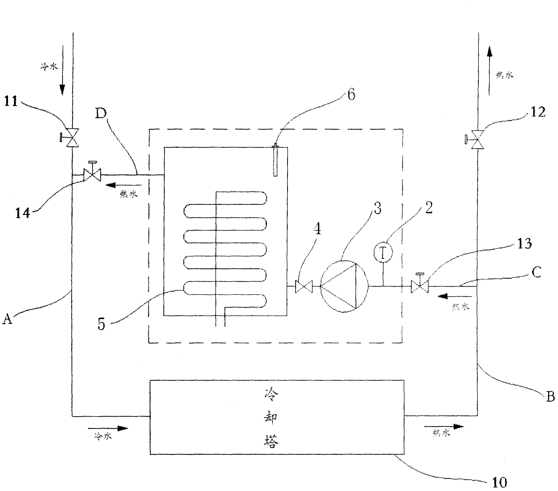
[0024] Such as figure 1 As shown, the figure includes a cooling tower water inlet pipe A, a cooling tower water outlet pipe B, and a closed cooling tower 10, and the dotted line box in the figure represents the antifreeze device. The water inlet pipe A of the cooling tower is connected to the water inlet end of the closed cooling tower 10, and the water outlet end of the closed cooling tower 10 is connected to the water outlet pipe B of the cooling tower. The antifreeze device includes an antifreeze inlet pipe C and an antifreeze outlet pipe D, the antifreeze inlet pipe C is connected to the cooling tower outlet pipe B, and the antifreeze outlet pipe D is connected to the cooling tower inlet pipe A. The cooling tower inlet pipe A is provided with a first valve 11, the cooling tower outlet pipe B is provided with a second valve 12, the antifreeze machine inlet pipe C is provided with a third valve 13, and the antifreeze machine outlet pipe D is provided with a fourth valve 14....


PUM


Abstract

The invention discloses an anti-freezing device for a closed cooling tower. The anti-freezing device comprises a water inlet pipe of the cooling tower and a water outlet pipe of the cooling tower, wherein the water inlet pipe of the cooling tower is connected to the water inlet end of the closed cooling tower, and the water outlet end of the closed cooling tower is connected with the water outlet pipe of the cooling tower. The anti-freezing device for the closed cooling tower is characterized by comprising an anti-freezing machine device. The anti-freezing machine device comprises a water inlet pipe of the anti-freezing machine and a water outlet pipe of the anti-freezing machine, wherein the water inlet pipe of the anti-freezing machine is connected with the outlet pipe of the cooling tower, the water outlet pipe of the anti-freezing machine is connected with the water inlet pipe of the cooling tower; the water inlet pipe of the cooling tower is provided with a first valve; the water outlet pipe of the cooling tower is provided with a second valve; the water inlet pipe of the anti-freezing machine is provided with a third valve; the water outlet pipe of the anti-freezing machine is provided with a fourth valve; and a pipeline at the back of the third valve is provided with a pump and a check valve successively in water flow direction. The anti-freezing device for the closed cooling tower is convenient to operate and reliable in work, can effectively prevent a coil pipe of the closed cooling tower from frost crack in winter, and ensures a normal operation of the closed cooling tower in winter.

Description

technical field [0001] The invention relates to the field of cooling tower antifreeze technology, in particular to a closed cooling tower antifreeze equipment. Background technique [0002] In the cold winter, when the closed cooling tower is not in operation, the cooling coil will often freeze due to the low temperature, resulting in internal freezing and cracking of the coil. As the core component of the closed cooling tower, the cooling coil will cause the closed cooling tower to fail to operate normally after being frozen and cracked. [0003] At present, the following two schemes are generally adopted for anti-freezing of closed cooling towers: one is to add antifreeze (ethylene glycol) inside the circulation pipeline; the other is to discharge the cooling water inside the circulation pipeline when the closed cooling tower is not in operation in winter . [0004] However, it has been proved that the above two solutions have different defects: the defect of the first s...

Claims


Application Information

Patent Timeline
Patent Type & Authority Applications(China)
IPC IPC(8): F28C1/10F28F17/00
Inventor 李麟添侯红立吴育新
Owner SHANGHAI KING SUN COOLING EQUIP
Why Eureka
Try Eureka