General vibration test fixture for track traffic electrical equipment and installation method of general vibration test fixture

A technology for vibration testing and electrical equipment, which is applied in vibration testing, measuring devices, and testing of machine/structural components. It can solve problems such as scrapped fixtures, waste of time and costs, and non-common use of test fixtures to improve work efficiency. , easy installation, saving test preparation time

Active Publication Date: 2015-06-10
ZHUZHOU CSR TIMES ELECTRIC CO LTD
View PDF6 Cites 0 Cited by
  • Summary
  • Abstract
  • Description
  • Claims
  • Application Information

AI Technical Summary

Problems solved by technology

Although these test pieces are installed on the base, because the connection holes between the test piece and the fixture, and the connection hole between the fixture and the vibrating table are not the same, the vibration test fixtures of various test pieces cannot be used in common. After the vibration test, it can only be scrapped and cannot be reused
The design, manufacture and transportation of fixtures take a certain amount of time, and the manufacture of fixtures also requires a certain amount of cost. Since each test fixture cannot be used universally, it leads to a great waste of time and cost.

Method used


Image

  • General vibration test fixture for track traffic electrical equipment and installation method of general vibration test fixture
  • General vibration test fixture for track traffic electrical equipment and installation method of general vibration test fixture
  • General vibration test fixture for track traffic electrical equipment and installation method of general vibration test fixture

Examples


Embodiment Construction

[0034] The following will clearly and completely describe the technical solutions in the embodiments of the present invention with reference to the accompanying drawings in the embodiments of the present invention. Obviously, the described embodiments are only part of the embodiments of the present invention, not all of them. Based on the embodiments of the present invention, all other embodiments obtained by persons of ordinary skill in the art without creative efforts fall within the protection scope of the present invention.

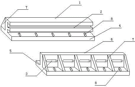
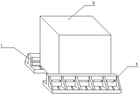
[0035] as attached figure 1 to attach Figure 10 As shown, a specific embodiment of a universal vibration test fixture for rail transit electrical equipment and its installation method of the present invention is provided. The present invention will be further described below in conjunction with the accompanying drawings and specific embodiments.

[0036] as attached figure 1 A general vibration test fixture for electrical equipment in rail transit ...


PUM


Abstract

The invention discloses a general vibration test fixture for track traffic electrical equipment and an installation method of the general vibration test fixture. The general vibration test fixture comprises an assembly part I and an assembly part II, and both the assembly part I and the assembly part II are formed by welding or integrally casting soleplates and vertical plates. The general vibration test fixture disclosed by the invention is characterized in that reinforcing ribs are arranged between the vertical plates and the soleplates, so that the integral rigidity is increased; the vertical plates of the assembly part I and the assembly part II are respectively provided with a T-shaped slot and long through holes I in the back and force direction (X direction), so that the installation requirement of screw holes in different spacings is satisfied; the soleplates of both the assembly part I and the assembly part II are provided with long through holes II in the left and right direction (Y direction), so that the installation requirement of screw holes of vibration table surfaces in different spacings is satisfied, therefore the generality of the fixture for track traffic electrical equipment of a base-mounted type is achieved. The general vibration test fixture disclosed by the invention is low in cost, high in resonance frequency, small in volume, light in weight, good in rigidity, convenient in installation and high in work efficiency, thereby having higher economic usefulness.

Description

technical field [0001] The invention relates to a vibration test fixture and an installation method thereof, in particular to a general vibration test fixture and an installation method thereof which can satisfy certain types of rail transit electrical equipment installed in a base mode. Background technique [0002] The function of the vibration test fixture is to connect the test piece and the vibration table, and transfer the motion and energy of the vibration table to the test piece. During the test, it is hoped that the vibrating table will transmit the vibration energy to the test piece through the fixture without distortion. A variety of rail transit electrical equipment installed in the equipment room of the electric locomotive is installed on the T-shaped slot welded to the car body through the base. [0003] At present, when this type of base-mounted electrical equipment is subjected to a vibration test, a fixture needs to be designed separately for each tested pi...

Claims


Application Information

Patent Timeline
Patent Type & Authority Patents(China)
IPC IPC(8): G01M7/02
Inventor 王鹏余锋陈彪张智刘国涛
Owner ZHUZHOU CSR TIMES ELECTRIC CO LTD
Why Eureka
Try Eureka