Power supply ripple interference test method and system
What is Al technical title?
Al technical title is built by PatSnap Al team. It summarizes the technical point description of the patent document.
A power supply ripple and interference test technology, which is applied in the direction of measuring electricity, measuring devices, and measuring electrical variables, etc., can solve the problems of low test efficiency and low measurement accuracy, improve test efficiency, improve accuracy, and reduce labor costs. The effect of the operation
Active Publication Date: 2012-12-19
INTERTEK TESTING SERVICES
View PDF9 Cites 12 Cited by
Summary
Abstract
Description
Claims
Application Information
AI Technical Summary
This helps you quickly interpret patents by identifying the three key elements:
Problems solved by technology
Method used
Benefits of technology
Problems solved by technology
[0005] The purpose of the present invention is to provide a power supply ripple interference test method and system, which is used to solve the problems of low test efficiency and low measurement accuracy in the prior art, so as to meet the requirements for efficiency in the power supply ripple interference test process of automotive electronic equipment. and precision requirements
Method used
Image
Click on the blue label to locate the original text in one second.
Reading with bidirectional positioning of images and text.
Examples
Embodiment Construction
[0022] The technical solutions of the embodiments of the present invention will be further described below in conjunction with the accompanying drawings and specific embodiments.
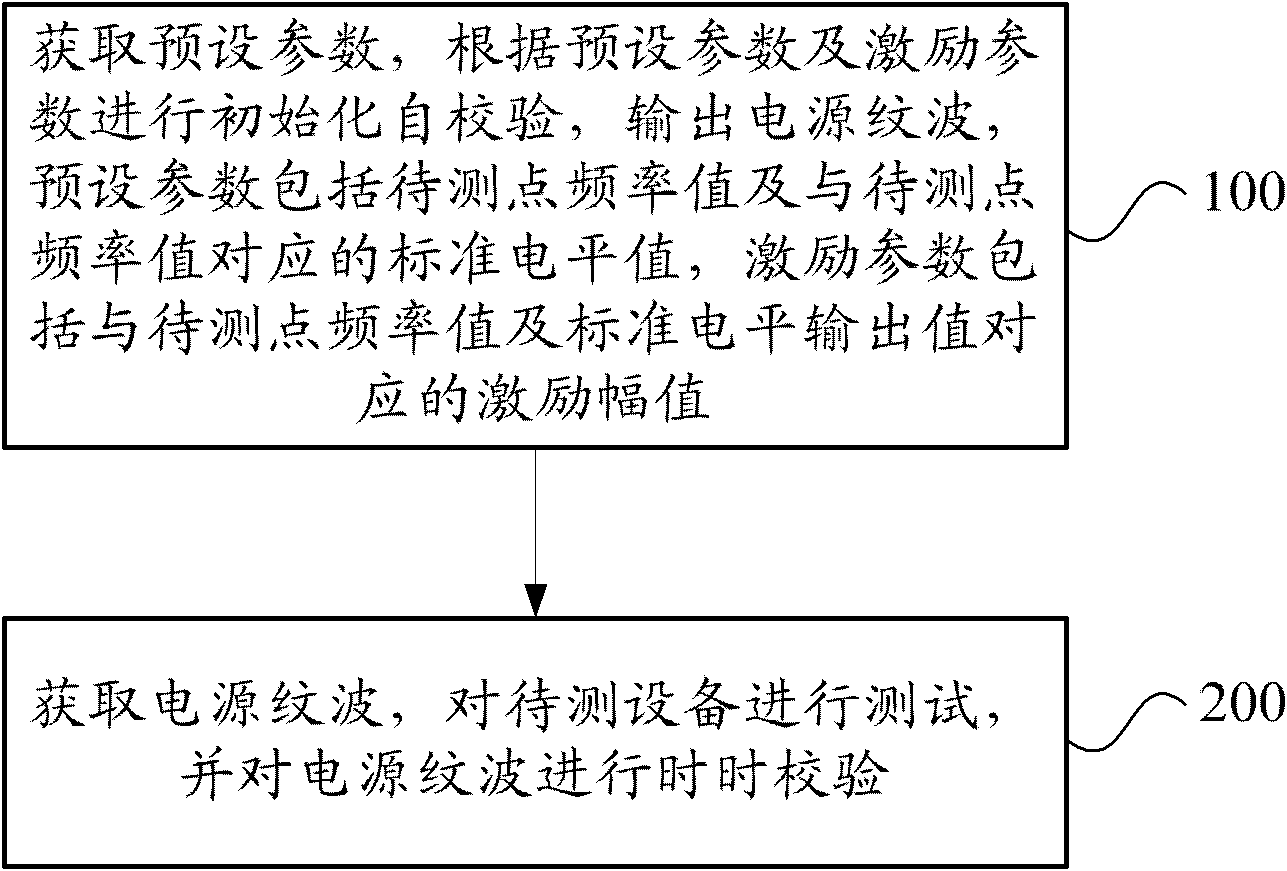
[0023] The invention provides a power supply ripple interference test method, figure 1 It is a schematic flow chart of an embodiment of the power supply ripple interference test method of the present invention, as figure 1 As shown, the method includes the following steps:
[0024] Step 100, obtain preset parameters, perform initialization self-checking according to the preset parameters and excitation parameters, and output power supply ripple, the preset parameters include the frequency value of the point to be measured and the standard level value corresponding to the frequency value of the point to be measured, and the excitation The parameters include the excitation amplitude corresponding to the frequency value of the point to be measured and the output value of the standard level. The user ...
PUM
Abstract
The invention provides a power supply ripple interference test method and system. The method comprises the steps of: obtaining preset parameters, carrying out initialization self-checking according to the preset parameters and an excitation parameter and outputting a power supply ripple, wherein the preset parameters comprise a frequency value of the point to be tested and a standard level value corresponding to the frequency value of the point to be tested, and the excitation parameter comprises an excitation amplitude value corresponding to the frequency value of the point to be tested and the standard level output value; and testing the equipment to be tested, and carrying out real-time verification on the power supply ripple. The system comprises an initialization self-checking module and a real-time verification and test module, wherein the initialization self-checking module is used for obtaining the preset parameters, carrying out initialization self-checking according to the preset parameters and the excitation parameter and outputting the power supply ripple; and the real-time verification and test module is used for obtaining the power supply ripple, testing the equipment to be tested, and carrying out real-time verification on the power supply ripple. By adopting the method and system, the testing efficiency and measurement accuracy are effectively improved, therefore, the efficiency and accuracy requirements in a power supply ripple interference test process of automobile electronic equipment are met.
Description
technical field [0001] The invention relates to a test method and system, in particular to a power supply ripple interference test method and system, belonging to the field of electronic communication. Background technique [0002] With the rapid development of the automobile industry and the electronics industry, more and more automotive electronic devices are appearing on the market. These automotive electronic devices, such as ignition coils, lights, indicator lights, wipers, windows, antenna lifters, Global Positioning System (Global Positioning System, referred to as: GPS), etc., realize extremely diverse functions inside the car. , Such as driving safety functions, indicating functions, anti-theft functions, control functions during driving, driver comfort adjustment functions and entertainment functions, etc. Today, automotive electronic equipment has played an irreplaceable role in improving vehicle power, economy, safety, driving stability and ride comfort. [000...
Claims
Application Information
Patent Timeline
Application Date:The date an application was filed.
Publication Date:The date a patent or application was officially published.
First Publication Date:The earliest publication date of a patent with the same application number.
Issue Date:Publication date of the patent grant document.
PCT Entry Date:The Entry date of PCT National Phase.
Estimated Expiry Date:The statutory expiry date of a patent right according to the Patent Law, and it is the longest term of protection that the patent right can achieve without the termination of the patent right due to other reasons(Term extension factor has been taken into account ).
Invalid Date:Actual expiry date is based on effective date or publication date of legal transaction data of invalid patent.