Motor gear identification method and device

An identification method and identification device technology, applied in the direction of motor generator testing, etc., can solve the problems of troublesome maintenance of circuit boards, low equipment integration, waste of construction materials, etc., to facilitate popularization, realize multi-port acquisition, and reduce construction difficulty Effect

Inactive Publication Date: 2012-12-19
ZHENGZHOU CHUNQUAN ENERGY SAVING
View PDF7 Cites 5 Cited by
  • Summary
  • Abstract
  • Description
  • Claims
  • Application Information

AI Technical Summary

Problems solved by technology

But its shortcomings are: 1. The circuit is relatively complicated. Taking the three-speed motor as an example, the detection of each motor requires three detections, and high, medium and low voltage signals must be collected, so the maintenance of the circuit board is relatively troublesome. , the cost is high; 2. Inconvenient to use, the construction is more complicated, a single motor takes up to five acquisition lines, waste of construction materials, and the cost is high; 3. A single motor takes up hardware resources (I / O ports of the CPU, etc.) More, so the degree of integration of the device is low, and the number of motors that can be detected by a single device is small
If it is applied to the running state detection of a larger number of multi-speed motors, the above shortcomings are more obvious

Method used


Image

  • Motor gear identification method and device
  • Motor gear identification method and device
  • Motor gear identification method and device

Examples


Embodiment 1

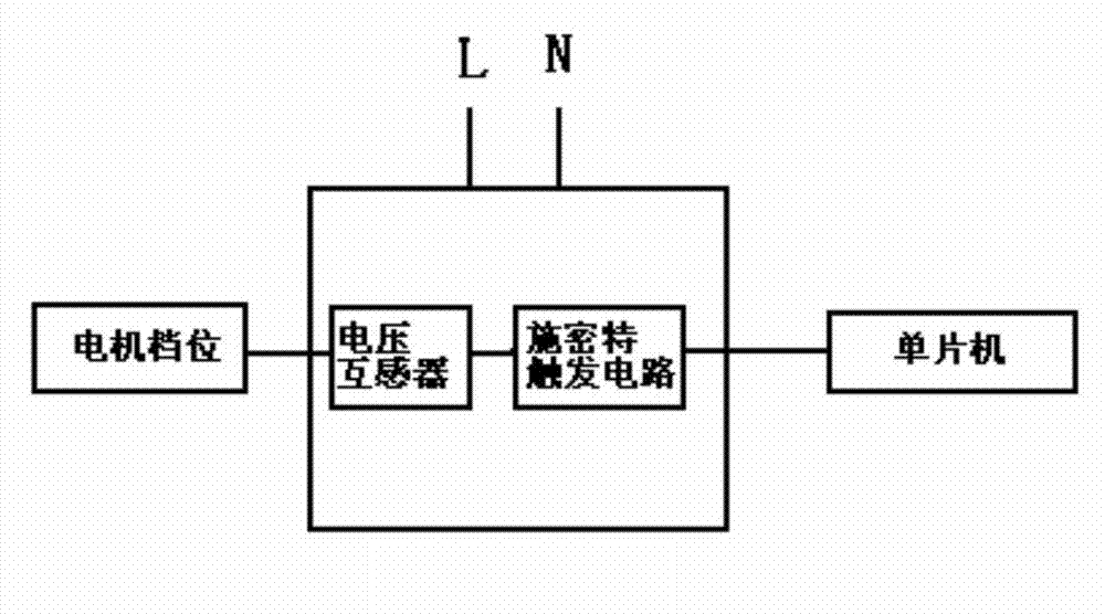
[0033] Embodiment one: see figure 1 , the motor gear identification method of the present invention, for a common zero winding multi-tap motor, by measuring the voltage induction pulse of any gear, and then according to the size of the voltage induction pulse width, compared with the standard pulse width, determine the motor stalls:

[0034] Based on the correction value of the induction pulse width ±0~N of any gear of the mains or fan, the high-grade is recorded as K1, the middle-range is K2, the mains is K3, and the low-grade is K4, where K4>K3> K2>K1, said N is a positive real number;

[0035] Measure the induction pulse width K of the low gear position of the motor. When K≤K3, it can be judged that the motor is running at a low gear position; when K3

Embodiment 2

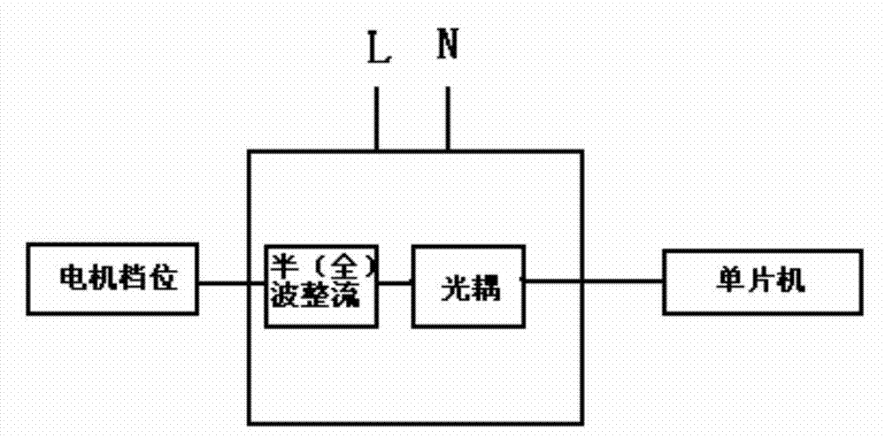
[0036] Embodiment two: see figure 2 , the motor stall identification method of this embodiment is different from Embodiment 1 in that by measuring the induction pulse width of the stall in the motor and comparing it with the standard pulse width, the stall of the motor is determined:

[0037] Based on the correction value of the induction pulse width ±0~N of any gear of the mains or fan, the high-grade is recorded as K1, the middle-range is K2, the mains is K3, and the low-grade is K4, where K4>K3> K2>K1, said N is a positive real number;

[0038] Measure the induction pulse width K of the middle gear of the motor. When K≤K2, it is judged that the motor is running at a low gear; when K2

Embodiment 3

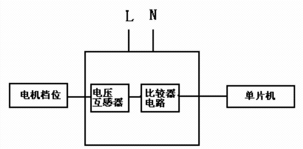
[0039] Embodiment three: see image 3 , the motor stall identification method of this embodiment is different from Embodiment 1 in that by measuring the induction pulse width of the stall in the motor and comparing it with the standard pulse width, the stall of the motor is determined:

[0040] Based on the correction value of the induction pulse width ±0~N of any gear of the mains or fan, the high-grade is recorded as K1, the middle-range is K2, the mains is K3, and the low-grade is K4, where K4>K3> K2>K1, said N is a positive real number;

[0041] Measure the induction pulse width K of the high gear of the motor. When K≤K1, it is judged that the motor is running at a low gear; when K1


PUM


Abstract

The invention relates to a motor gear identification method, and particularly relates to a simple motor gear identification method and device based on a voltage mutual inductance technology. The motor gear identification method comprises the steps of: measuring a voltage induction pulse at any gear of a common zero winding multi-tap motor, then comparing with a standard pulse width according to the size of the voltage induction pulse width, determining the gear of the motor, and applying the gear to a common zero multi-gear speed multi-winding motor, for example, detection of an operating state of a three-gear speed fan coil of a central air conditioner. The operating state of the motor can be quickly and reliably identified. The gear identification is achieved by voltage induction pulse width size relationship of different gears of the motor winding; the motor gear identification method is easy to implement and high in accuracy; meanwhile, the motor gear identification device just requires a group of gear connection wires, so that the structure of the device is simplified; the cost is low; the construction difficulty in application is reduced; the social resource is saved, and generalization is convenient.

Description

technical field [0001] The invention relates to a method for identifying a gear position of a motor, in particular to a simple method and device for identifying a gear position of a motor based on voltage mutual inductance technology. Applied to zero multi-speed multi-winding motors, such as the detection of the running status of central air-conditioning three-speed fan coils. Background technique [0002] With the continuous advancement of social science and technology, the chemical, petroleum, electronics, and automobile industries have already realized the automatic control of the production process, making indelible contributions to the development of the national economy. However, for households and civil utilities, remote billing and meter reading systems for water, electricity, gas, and heating have not yet been popularized, and some have just started. With the reform and opening up of the society and the further development of the market economy, in order to realize...

Claims


Application Information

Patent Timeline
IPC IPC(8): G01R31/34
Inventor 黄守峰樊晓翠陈玉军杨东陈传伟
Owner ZHENGZHOU CHUNQUAN ENERGY SAVING
Why Eureka
Try Eureka