
An inductor module and its base

A technology of inductors and bases, applied in the field of inductors, can solve problems such as increasing strength

Inactive Publication Date: 2015-12-09
DELTA ELECTRONICS INC
View PDF5 Cites 0 Cited by
  • Summary
  • Abstract
  • Description
  • Claims
  • Application Information

AI Technical Summary

Problems solved by technology

[0007] Therefore, the main purpose of the present invention is to solve the shortcomings of the existing inductor structure. The present invention redesigns the inductor structure to make the process simpler and easier, and can reduce the height requirement on the circuit board after the overall assembly of the inductor structure , the positioning piece has a hook-shaped design, which increases the strength of the combination, and does not need to dispense glue to fix the inductance element, which can reduce the material of glue and the man-hours required for glue dispensing. The wire after the winding is directly connected to the base. The conductive pins are electrically connected, so there will be no more shaking problems, making the pitch of the pins more accurate

Method used


Image

  • An inductor module and its base
  • An inductor module and its base
  • An inductor module and its base

Examples


Embodiment Construction

[0063] The technical content and detailed description of the present invention are now described as follows in conjunction with the accompanying drawings:

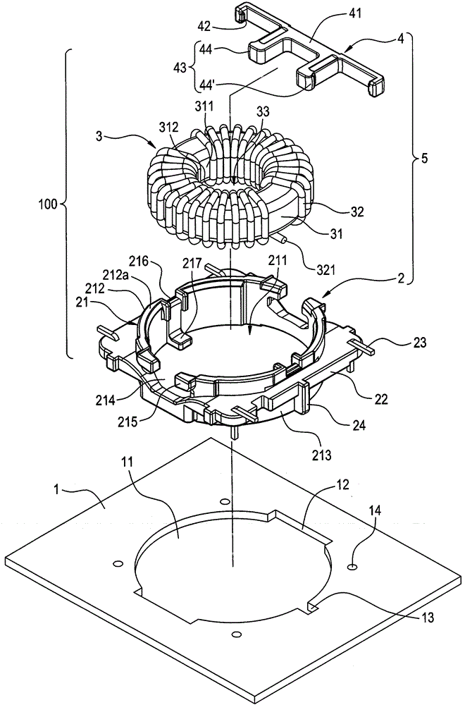
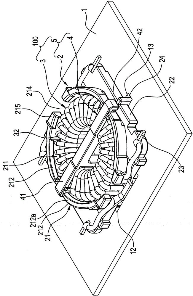
[0064] see figure 2 and image 3 , as shown in the figure, the inductor module 100 of the present invention is disposed on a circuit board 1 , the inductor module 100 includes an inductive element 3 and a base 5 , and the base 5 includes a base 2 and a positioning member 4 .

[0065] The circuit board 1 has a circular opening 11 , and two symmetrical recesses 12 and a foolproof notch 13 are formed on the periphery of the opening 11 . In addition, the circuit board 1 has a plurality of through holes 14 adjacent to the opening 11 .

[0066] The base 2 is assembled in the opening 11 of the circuit board 1 . The base 2 has an accommodating portion 21 , an extending portion 22 , four conductive pins 23 and a bump 24 . The accommodating portion 21 has an accommodating space 211 inside. The inductance element 3 is accommodat...


PUM


Abstract

The invention discloses an inductor module and a base of the inductor module. The inductor module comprises a base and an inductor element, wherein coils of the inductor element are electrically connected with conductive pins of a pedestal after installing the inductor element on the pedestal of the base; a positioning part of the base is assembled on the pedestal for fixing the inductor element; and then the pedestal is installed in an opening of a circuit board for reducing height of the inductor module above the circuit board after assembling the base with the circuit board. The positioning part is designed in an inverse hook shape, so that intensity of the positioning part can be increased after being assembled with the pedestal without fixing the inductor element by dispensing glue, therefore, a material of the glue and a labor hour for dispensing the glue can be reduced.

Description

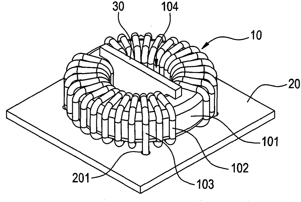
technical field [0001] The invention relates to an inductor, in particular to an inductor module capable of positioning the height of an inductance element on a circuit board and a base thereof. Background technique [0002] Existing inductor structures (such as figure 1 Shown) is a horizontal inductor 10, which has an annular iron core 101 on which a group of coils 102 are wound. sexual connection. A separator 30 is inserted into the annular hole 104 of the iron core 101 of the inductor 10 . When this existing inductor structure is manufactured, there are the following deficiencies: [0003] 1. The process of the existing inductor structure is complicated, and many process man-hours and processes are required. [0004] 2. The existing inductor 10 is directly electrically connected to the circuit board 20, so that the overall height of the inductor 10 on the circuit board 20 is too high, which cannot meet the current trend of electrical products towards thinner and short...

Claims


Application Information

Patent Timeline
Patent Type & Authority Patents(China)
IPC IPC(8): H01F27/06H05K3/30H01F17/06
Inventor 曾祥益田庆相
Owner DELTA ELECTRONICS INC
Learn More