
Circuit unit structure for process monitoring

A technology of circuit components and series structure, which is applied in the direction of circuits, electrical components, electric solid devices, etc., can solve problems such as the evaluation error of through-hole resistance value, and achieve the effect of improving correct evaluation, reducing negative effects, and improving reliability

Active Publication Date: 2012-12-19
SILICONWARE PRECISION IND CO LTD
View PDF4 Cites 0 Cited by
  • Summary
  • Abstract
  • Description
  • Claims
  • Application Information

AI Technical Summary

Problems solved by technology

However, for advanced semiconductor manufacturing technologies, such hole chain topology will be significantly affected by tip discharge effects and radio frequency coupling or crosstalk effects
For example, figure 1 The rectangular hole chain shown has the advantage of saving size and area, but for high frequency signal testing, such as AC or RF signal testing, this type of design has some limitations. figure 1 The two non-ideal effects shown: that is, if the high-frequency signal passes through the right angle R, the high-frequency signal will be radiated in the air, causing the signal not to pass through the hole chain; secondly, in the two hole chains or There may be, for example, parasitic capacitance Cp between the transmission lines, causing high-frequency signals to pass through the parasitic capacitance Cp instead of passing through the hole chain
[0005] Specifically, when the above-mentioned AC or radio frequency test is performed, the signal will be radiated into the air through the right angle R or pass through the parasitic capacitance Cp, which will cause errors in the evaluation of the via resistance.

Method used


Image

  • Circuit unit structure for process monitoring
  • Circuit unit structure for process monitoring
  • Circuit unit structure for process monitoring

Examples


Embodiment Construction

[0019] The technical content of the present invention is described below through specific specific embodiments, and those skilled in the art can easily understand other advantages and effects of the present invention from the content disclosed in this specification. The present invention can also be implemented or applied through other different specific embodiments, and various modifications and changes can be made to the details in this specification based on different viewpoints and applications without departing from the spirit of the present invention.

[0020] It should be noted that the structures, proportions, sizes, etc. shown in the drawings attached to this specification are only used to match the content disclosed in the specification for the understanding and reading of those skilled in the art, and are not intended to limit the scope of the present invention. Therefore, it has no technical substantive meaning, and any modification of structure, change of proportio...


PUM


Abstract

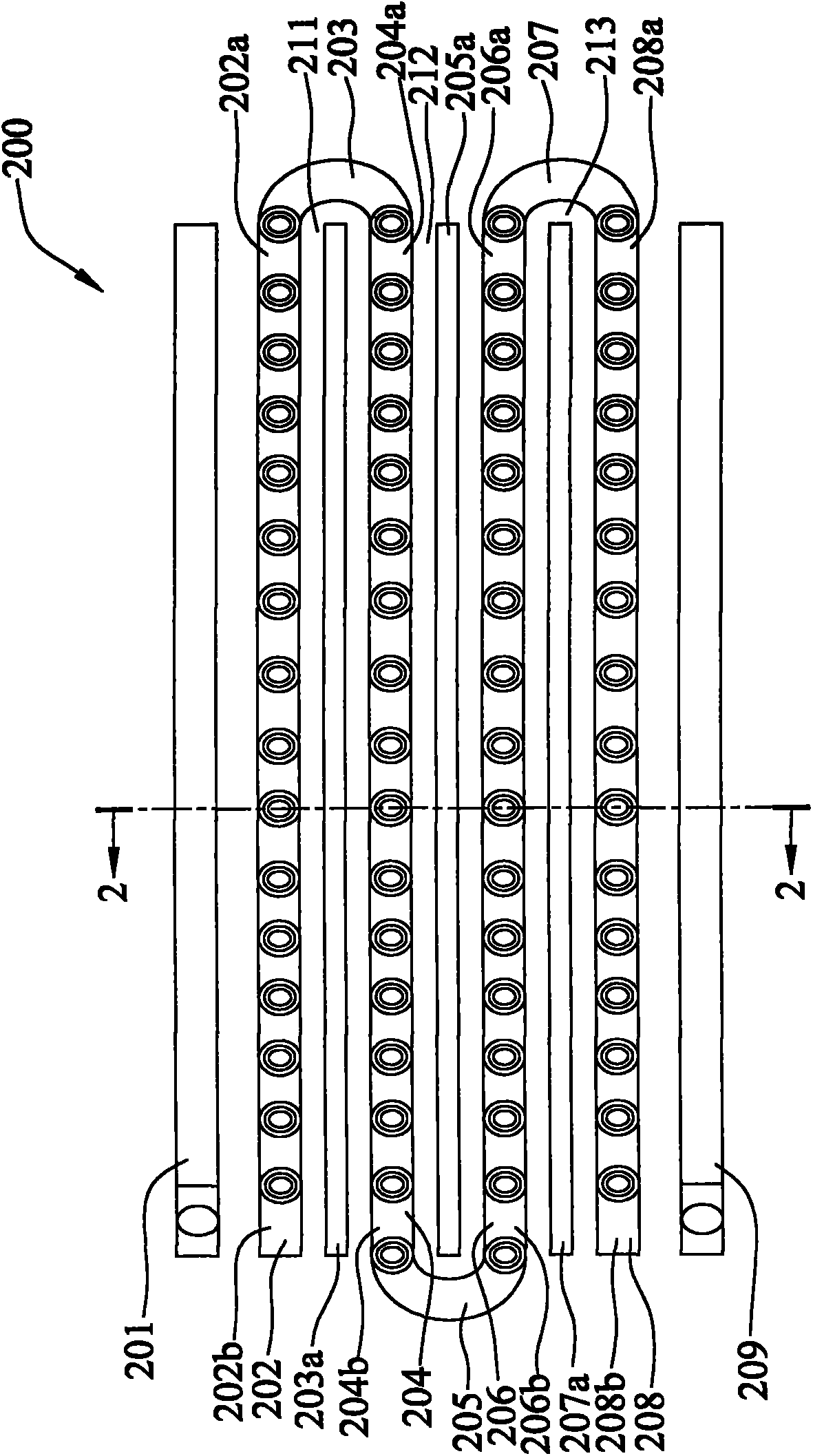
A circuit unit structure for process monitoring, especially a circuit unit structure applied to advance integrated circuit processing for integrated circuit testing and process monitoring, compared with conventional circuit unit structure, comprises a plurality of pore chains, a floating metal layer and an arc-shaped connection part, and is capable of notably reducing point discharge and radio frequency coupling or crosstalk effect during interflow or radio frequency testing processes, and preventing a too huge parasitic capacitance Cp from existing among the pore chains, thereby preventing assessment errors of via-hole resistance values from occurring, and further promoting reliability degree of the overall integrated circuit processing and testing.

Description

technical field [0001] The invention relates to an integrated circuit manufacturing process and an integrated circuit testing structure, especially a circuit component structure used in advanced semiconductor manufacturing processes as a test circuit and process monitoring. Background technique [0002] Due to the increasingly important trend of various portable (portable) electronic products such as communication, network, and computer and their peripheral products, and these electronic products are also developing in the direction of multi-function and high performance, the semiconductor manufacturing process is constantly moving towards Higher integration process evolution and high-density assembly structure are the goals pursued by the industry. As a result, reliability testing of manufactured semiconductor chips with higher densities becomes more and more important. [0003] In order to achieve the purpose of testing the reliability of the semiconductor chip, it is usu...

Claims


Application Information

Patent Timeline
IPC IPC(8): H01L23/544
Inventor 陈冠宇方柏翔蔡明汎李信宏
Owner SILICONWARE PRECISION IND CO LTD
Learn More