
Structure and layout method of circuit module via chain

A technology of circuit components and layout methods, which is applied to the components of electrical measuring instruments, measuring electricity, and measuring electrical variables, etc., can solve problems such as evaluation errors of through-hole resistance values, improve reliability, reduce radio frequency coupling and crosstalk effect of effect

Inactive Publication Date: 2012-12-05
SILICONWARE PRECISION IND CO LTD
View PDF4 Cites 2 Cited by
  • Summary
  • Abstract
  • Description
  • Claims
  • Application Information

AI Technical Summary

Problems solved by technology

[0005] Specifically, for this type of hole chain, when the above-mentioned AC or RF test is performed, the signal will pass through the edge parasitic capacitance Cp, which will cause errors in the evaluation of the via resistance value (viaresistance)

Method used


Image

  • Structure and layout method of circuit module via chain
  • Structure and layout method of circuit module via chain
  • Structure and layout method of circuit module via chain

Examples


no. 1 example

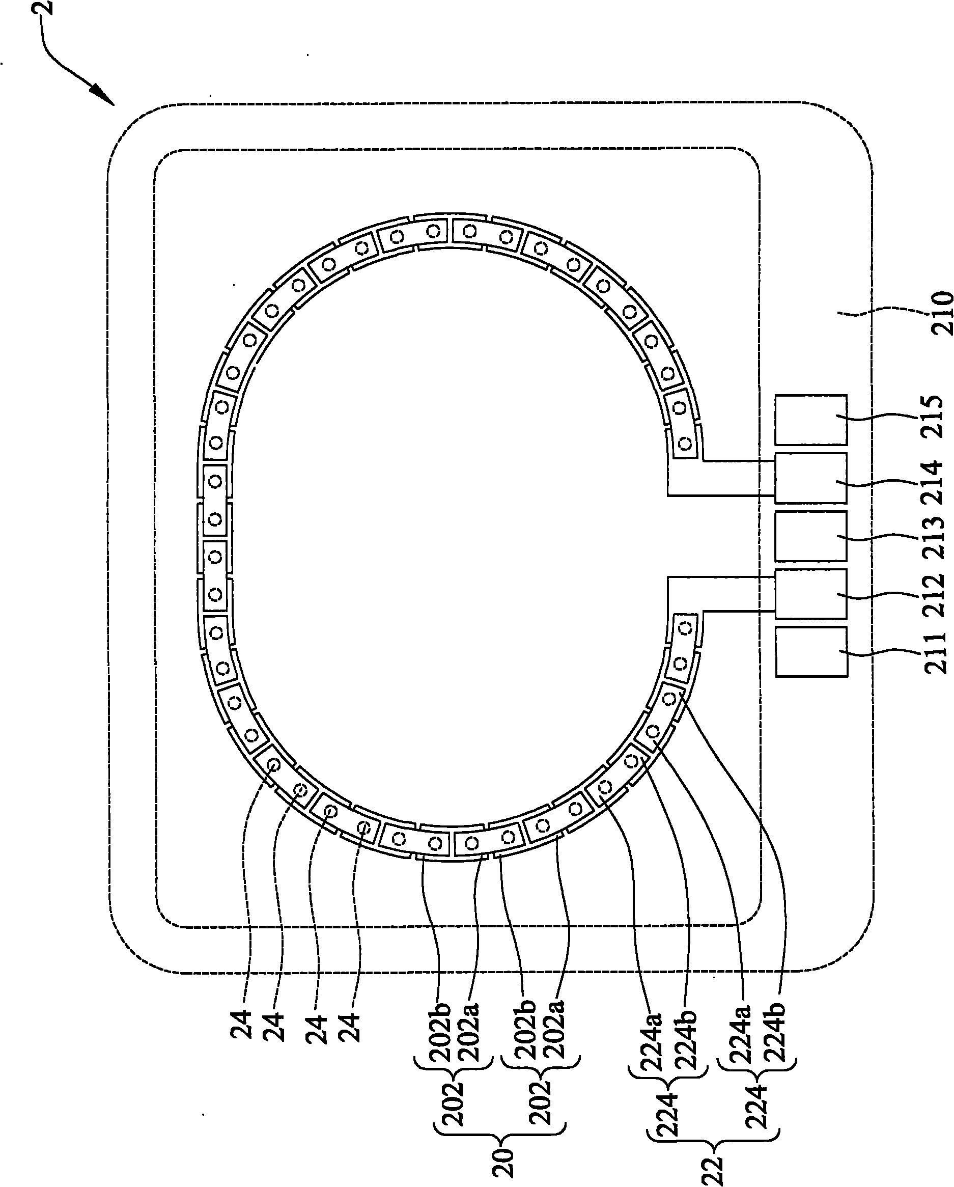
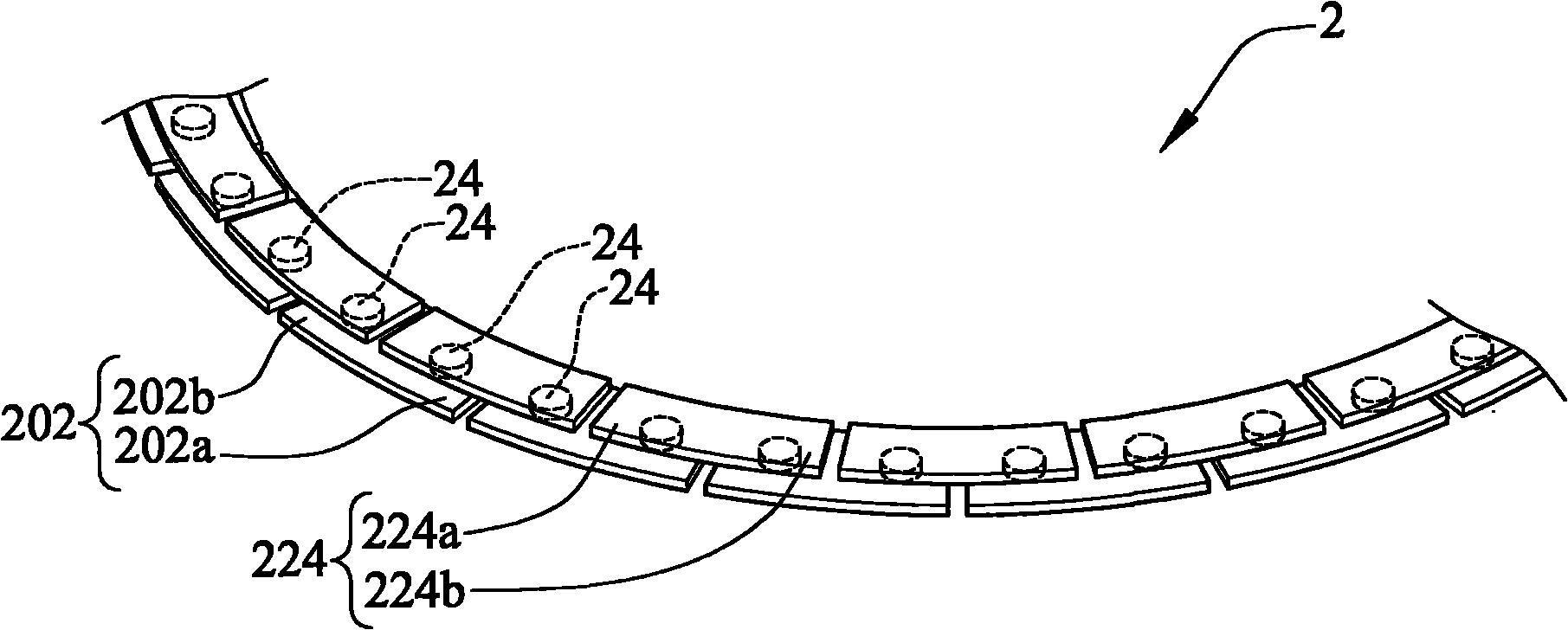
[0038] Please refer to Figure 2A and Figure 2B , which is a top view and a partial perspective view of the hole chain structure 2 of the circuit assembly in the first embodiment of the present invention. As shown in the figure, the hole chain structure 2 of the circuit component is a ring-shaped structure, and has a first metal layer 20, a second metal layer 22 and a plurality of through holes 24 formed on the first metal layer 20. The second metal layer 22 is located above the first metal layer 20 , wherein the first metal layer 20 has a plurality of first metal sheets 202 , and the second metal layer 22 has a plurality of second metal sheets 224 .

[0039] The plurality of first metal sheets 202 are arranged in a ring shape at appropriate intervals, and two adjacent first metal sheets 202 are arranged head to tail to form a ring structure. For example, as shown in the figure, the plurality of first metal sheets 202 each have a first end point 202a and a second end point ...

no. 2 example

[0051] Please refer to Figure 4 , which is a top view of the hole chain structure 4 of the circuit assembly according to the second embodiment of the present invention. Compared with the circuit component hole chain structure of the first embodiment, except that the ground ring 210 and the ground pads 211, 213, 215 are omitted, the circuit component hole chain structure 4 is different in that the first metal sheet 402 The shape is not a regular rectangle. The circuit component hole chain structure 4 is also composed of a plurality of first metal sheets 402 , a plurality of second metal sheets 424 and a plurality of through holes 44 .

[0052] What this embodiment intends to emphasize is that the hole chain structure of the circuit component is not limited to the shapes of the first metal sheets 402 and the second metal sheets 424 or even the shapes of the through holes 44, the main purpose is to avoid or reduce edge parasitic Capacitor Cp reduces RF coupling and crosstalk e...


PUM


Abstract

A structure and a layout method of a circuit module via chain can be applied to an advanced integrated circuit manufacture procedure and an integrated circuit test, an compared with existing via chain structures, the circuit module via chain structure in the invention comprises a plurality of metal sheets which are annularly arranged, can significantly improve RF coupling and reduce crosstalk effects, in terms of the circumstance of feeding in AC signals or RF signals for testing, can prevent existing of fringing parasitic capacitance Cp of a certain degree, prevent an error in estimating a resistance value of a via, and further improve the overall integrated circuit manufacture procedure and the testing reliability.

Description

technical field [0001] The invention relates to an integrated circuit manufacturing process and an integrated circuit test structure, in particular to a hole chain structure of a circuit component used as a test circuit and a layout method thereof. Background technique [0002] Due to the increasingly important trend of various portable electronic products such as communication, network, and computer and their peripheral products, and the development of these electronic products in the direction of multi-function and high performance, the semiconductor manufacturing process is It is constantly evolving towards a more integrated process, and a high-density assembly structure is the goal pursued by the industry. As a result, reliability testing of manufactured semiconductor chips with higher densities becomes more and more important. [0003] In order to achieve the purpose of testing the reliability of the semiconductor chip, it is usually necessary to set a test circuit on ...

Claims


Application Information

Patent Timeline
IPC IPC(8): H01L21/66G01R1/02
Inventor 陈冠宇方柏翔蔡明汎李信宏
Owner SILICONWARE PRECISION IND CO LTD
Learn More