Temperature control system for battery packs

A control system and battery pack technology, applied in battery pack components, secondary batteries, circuits, etc., can solve the problems of low convection heat transfer coefficient, poor battery heating effect, inconvenient maintenance and maintenance, and achieve uniform temperature change, Good isolation and simple structure

Inactive Publication Date: 2015-04-22
SOUTH CHINA UNIV OF TECH
View PDF5 Cites 0 Cited by
  • Summary
  • Abstract
  • Description
  • Claims
  • Application Information

AI Technical Summary

Problems solved by technology

[0003] ① thermal safety issues;
[0004] ② Thermal efficiency issues;
[0005] ③ Service life problem;
[0007] ⑤Applicability of high and low temperature environment
Gas cooling is more convenient and cheap, but its convective heat transfer coefficient is low, and the cooling effect is not good, especially in cold and low temperature environments, the heating effect on the battery is very poor
The convective heat transfer coefficient of oil is large, and the heat dissipation effect is good. However, the current liquid cooling structure needs to design special cooling pipes and heating pipes for certain battery packs. The structure is complex, the cost is high, and there are leaks, repair and maintenance. Disadvantages such as inconvenience
The phase change material cooling method has high requirements on the phase change material, and it is only effective in limiting the maximum and minimum temperature of the power battery, but it shows greater limitations at some high and low temperatures, and the phase change material It has a certain service life and must be replaced after a certain number of uses, so its cost is relatively high

Method used


Image

  • Temperature control system for battery packs
  • Temperature control system for battery packs
  • Temperature control system for battery packs

Examples


Embodiment

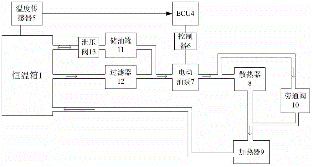
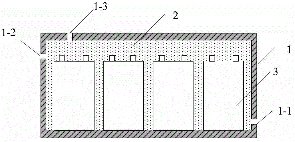
[0038] Such as figure 1 and figure 2 As shown, a battery pack temperature control system in this embodiment includes a battery pack 3, an ECU 4, a constant temperature box 1 filled with insulating oil, a radiator 8, a heater 9, an oil pump controller 6, an electric oil pump 7, an oil storage Tank 11 and oil filter 12, the insulating oil used in this embodiment is transformer oil.

[0039] The battery pack 3 is completely immersed in the transformer oil 2 in the constant temperature box 1, which reduces the temperature difference generated by each part of the battery pack 3, makes the temperature change of each part of the battery pack 3 more uniform, and improves the thermal efficiency of the battery pack 3. At the same time, the transformer oil as the insulating oil can also play the role of insulation and arc extinguishing, preventing fire and burning when the battery leaks, and improving the safety of the system in this embodiment.

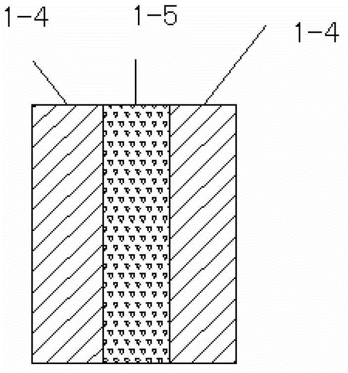
[0040] The constant temperature box 1...


PUM


Abstract

The invention discloses a temperature control system for battery packs. The temperature control system for the battery packs comprises the battery packs, an ECU (electronic control unit), a constant-temperature tank filled with insulated oil liquid, an oil liquid filter, a radiator, a heater, an oil pump controller and an oil pump. The constant-temperature tank is provided with an oil outlet and an oil inlet, a plurality of temperature sensors are arranged on the surface of the constant-temperature tank, the temperature sensors, the radiator, the heater and the oil pump controller are respectively electrically connected with the ECU, the oil pump is connected with the oil pump controller, the oil liquid filter is respectively communicated with the oil outlet of the constant-temperature tank and an oil inlet of the oil pump through pipelines, an oil outlet of the oil pump is communicated with the radiator through a pipeline, and the heater is respectively communicated with the oil inlet of the constant-temperature tank and the radiator through pipelines. The temperature control system for the battery packs has the advantages of simple structure, low cost, high safety and the like, the temperature of the battery packs can be constantly controlled within a normal working temperature range, working efficiency of the battery packs is effectively improved, and the service life of the battery packs is effectively prolonged.

Description

technical field [0001] The invention belongs to the field of temperature control, in particular to a battery pack temperature control system. Background technique [0002] People's increasing concern about environmental pollution and energy consumption has accelerated the development of new energy vehicles. However, the development of new energy vehicles is facing multiple problems, and the battery pack problem has become one of the important problems that need to be solved urgently. The battery pack problems mainly include: [0003] ① thermal safety issues; [0004] ② Thermal efficiency issues; [0005] ③ Service life problem; [0006] ④ The temperature difference of the battery cells in the battery pack caused by temperature; [0007] ⑤ The applicability of high and low temperature environment. [0008] In order to better deal with the above problems, it is necessary to design the necessary temperature control system for the battery pack. [0009] The temperature con...

Claims


Application Information

Patent Timeline
Patent Type & Authority Patents(China)
IPC IPC(8): H01M2/10H01M10/617H01M10/625H01M10/635H01M10/6567H01M10/658
CPCY02E60/10
Inventor 罗玉涛谭迪
Owner SOUTH CHINA UNIV OF TECH
Why Eureka
Try Eureka