
Pulse signal unilateral edge time delay circuit

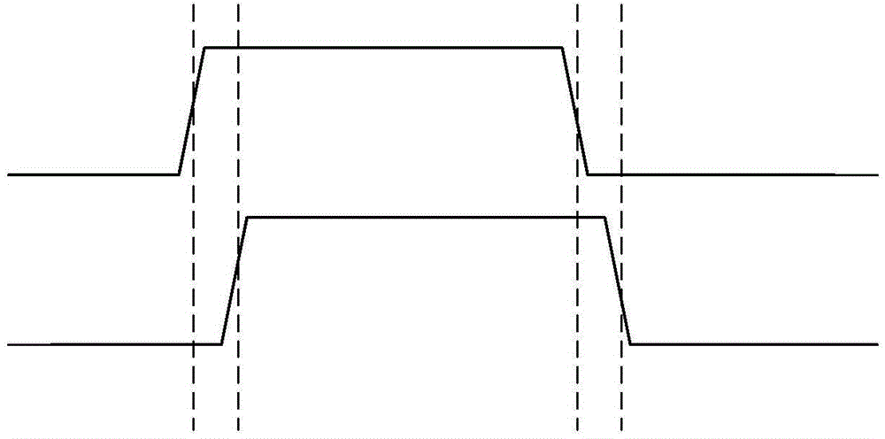
A pulse signal, one-sided technology, applied in pulse processing, pulse technology, electrical components, etc., can solve problems such as poor digital signal integrity, achieve good digital integrity, reduce power output capability requirements, and realize pulse single-sided edge delay when the effect

Inactive Publication Date: 2015-03-25
无锡中科沃谱瑞科技有限责任公司
View PDF5 Cites 0 Cited by
  • Summary
  • Abstract
  • Description
  • Claims
  • Application Information

AI Technical Summary

Problems solved by technology

Compared with resistors and capacitors, the constant current source circuit can suppress the influence of circuit temperature characteristics and power supply voltage on the edge delay, but the current constant current source pulse delay technology has poor digital signal integrity, and the rising and falling edges of the input pulse are both sides Latency Disadvantages

Method used


Image

  • Pulse signal unilateral edge time delay circuit
  • Pulse signal unilateral edge time delay circuit
  • Pulse signal unilateral edge time delay circuit

Examples


Embodiment Construction

[0024] Preferred embodiments of the invention will now be described in more detail with reference to the accompanying drawings, in which preferred embodiments of the invention are shown. However, the present invention may be embodied in various forms and should not be construed as limited to the embodiments set forth herein. Rather, these embodiments are provided so that this disclosure will be thorough and complete, and will fully convey the scope of the invention to those skilled in the art.

[0025] Image 6 The circuit schematic diagram of the existing constant current source pulse delay circuit is shown. according to Image 6 , the circuit includes: first stage inverter U2, second stage inverter U3, a pair of switches MP1 and MN1, constant current source I0, capacitor C0, third switch MN2, fourth switch MP0, voltage comparator U0 and inverter U1, where

[0026] After the input pulse IN passes through the first-stage inverter U2 to obtain the inversion signal inn, it t...


PUM


Abstract

The invention discloses a pulse signal unilateral edge time delay circuit which comprises a first-level phase inverter U82, a second-level phase inverter U83, two pairs of transistor switches, a constant flow source I0, a capacitor C80, a fifth switch MP80, a voltage comparator U80 and a nor-logic element U81; at the input pulse low electric level stage, the constant flow source I0 charges for the capacitor C80 through controlled transistors; after input pulse rising edge comes, electric charge stored by the capacitor C80 through a discharge switch by utilizing the constant flow source I0 is subjected to linear discharge; and the voltage comparator U80 detects the voltage of the capacitor C80 and obtains unilateral time delay pulse signal together with the input signal reverse signal through the nor-logic element U81. The circuit provided by the invention achieves unilateral edge time delay, and has the advantages of long time delay per capacitor, flexible time delay regulation and good digital signal completeness.

Description

technical field [0001] The invention relates to an edge delay circuit of a pulse signal, in particular to a circuit which uses a constant current source to discharge a charging capacitor to realize pulse single-side edge delay. Background technique [0002] The pulse delay circuit is a functional circuit that can extend the rising edge and / or falling edge of the pulse signal for a certain period of time before outputting. figure 1 shows the input and output pulse waveforms of typical pulse one-sided delays, as figure 1 As shown, the output pulse on the right side of the "pulse edge delay circuit" is compared with the input pulse on the left side, and the rising edge of the pulse is delayed to a certain moment before it appears. figure 1 The signal waveform on the right shows that the output pulse has a one-sided delay characteristic, or rising edge delay, relative to the input pulse. [0003] In the more general case, figure 2 The input and output pulse waveforms of comm...

Claims


Application Information

Patent Timeline
Patent Type & Authority Patents(China)
IPC IPC(8): H03K5/14H03K17/28H03K5/134
Inventor 卢小冬杨连军刘禹张海英
Owner 无锡中科沃谱瑞科技有限责任公司
Learn More