Sensitivity test method and device
A test method and sensitivity technology, applied in the field of communication, can solve problems such as the inability to balance test accuracy and efficiency, and achieve the effect of improving test efficiency and precision
- Summary
- Abstract
- Description
- Claims
- Application Information
AI Technical Summary
Problems solved by technology
Method used
Image

Examples
Embodiment 1
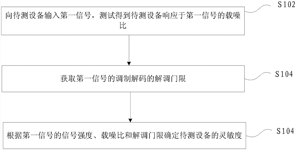
[0022] The embodiment of the present invention provides a method for testing the sensitivity of a device to be tested, and the method can be used for automatic measurement of wireless products. figure 1 It is a flow chart of the testing method for the sensitivity of the device under test according to an embodiment of the present invention, such as figure 1 As shown, the method includes the following steps:
[0023] Step S102, input the first signal to the device under test, and test to obtain the carrier-to-noise ratio of the device under test in response to the first signal; wherein, the device under test includes but not limited to wireless devices;
[0024] Step S104, acquiring a demodulation threshold for modulation and decoding of the first signal;
[0025] Step S106, determining the sensitivity of the device under test according to the signal strength, carrier-to-noise ratio and demodulation threshold of the first signal.
[0026] In general, sensitivity means that the...
Embodiment 2
[0035] The purpose of this embodiment is to provide a method for quickly and accurately measuring sensitivity, the principle of which will be described in detail below.
[0036] When testing the sensitivity, first input a strong signal arbitrarily, and then measure the packet error rate (PacketErrorRate, referred to as PER) of the product. Usually, the PER at this time is 0. Therefore, it is difficult to determine the signal strength in the next step based on this value. How much to adjust to get close to the sensitivity. However, if the carrier-to-noise ratio of the signal to be demodulated is counted at this time, the sensitivity of the product can be calculated according to the demodulation threshold of the signal (for a certain modulation and coding method, this is a predictable constant). The principle is as follows:
[0037] Let the stronger signal strength of any input be S i1 (dBm), the thermal noise energy at the input port is N i (dBm), then the signal-to-noise ra...
Embodiment 3
[0049] This embodiment is a further optimization of Embodiment 1, and the implementation process of this embodiment will be described in detail below.
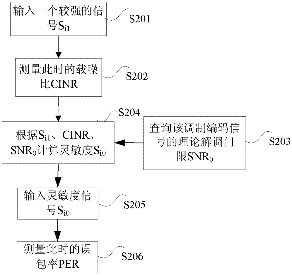
[0050] figure 2 It is a flow chart of the test method for the sensitivity of the device under test according to Embodiment 3 of the present invention, such as figure 2 As shown, the method includes the following steps:
[0051] Step S201, input a strong signal of arbitrary strength (for example, a signal 10-30dB higher than the estimated sensitivity), set the strength of the signal as S i1 (dBm).
[0052] In step S202, the carrier-to-noise ratio when measuring the signal strength is set as CINR (dB).
[0053] Step S203, query the theoretical demodulation threshold SNR of the signal according to the modulation and coding method of the input signal 0 .
[0054] Step S204, according to S i0 = S i1 +(SNR 0 -SNR 1 )=S i1 +[SNR 0 -10lg (10 CINR / 10 -1)] Calculate the sensitivity level S i0 .
[0055] Step S205, modify...
PUM
 Abstract
Description
Claims
Application Information
 - R&D
- Intellectual Property
- Life Sciences
- Materials
- Tech Scout
- Unparalleled Data Quality
- Higher Quality Content
- 60% Fewer Hallucinations
Browse by: Latest US Patents, China's latest patents, Technical Efficacy Thesaurus, Application Domain, Technology Topic, Popular Technical Reports.
© 2025 PatSnap. All rights reserved.Legal|Privacy policy|Modern Slavery Act Transparency Statement|Sitemap|About US| Contact US: help@patsnap.com