Ultrasonic transducer with piezoelectric element and distance sensor

A technology of ultrasonic transducers and piezoelectric elements, applied in the direction of sensors, electrical components, sensor types, etc., can solve problems such as complex steps and affecting signal quality, and achieve the effect of low cost and reduced susceptibility to interference

Active Publication Date: 2012-12-19
ROBERT BOSCH GMBH
View PDF4 Cites 3 Cited by
  • Summary
  • Abstract
  • Description
  • Claims
  • Application Information

AI Technical Summary

Problems solved by technology

In the case of this signal strength, small electromagnetic interference can also significantly affect the signal quality
[0004] Furthermore, for example in DE 102 61 033 A1 a connection structure is known, which is based on a multi-core cable, but this entails complex steps in the automated production

Method used


Image

  • Ultrasonic transducer with piezoelectric element and distance sensor
  • Ultrasonic transducer with piezoelectric element and distance sensor

Examples


Embodiment Construction

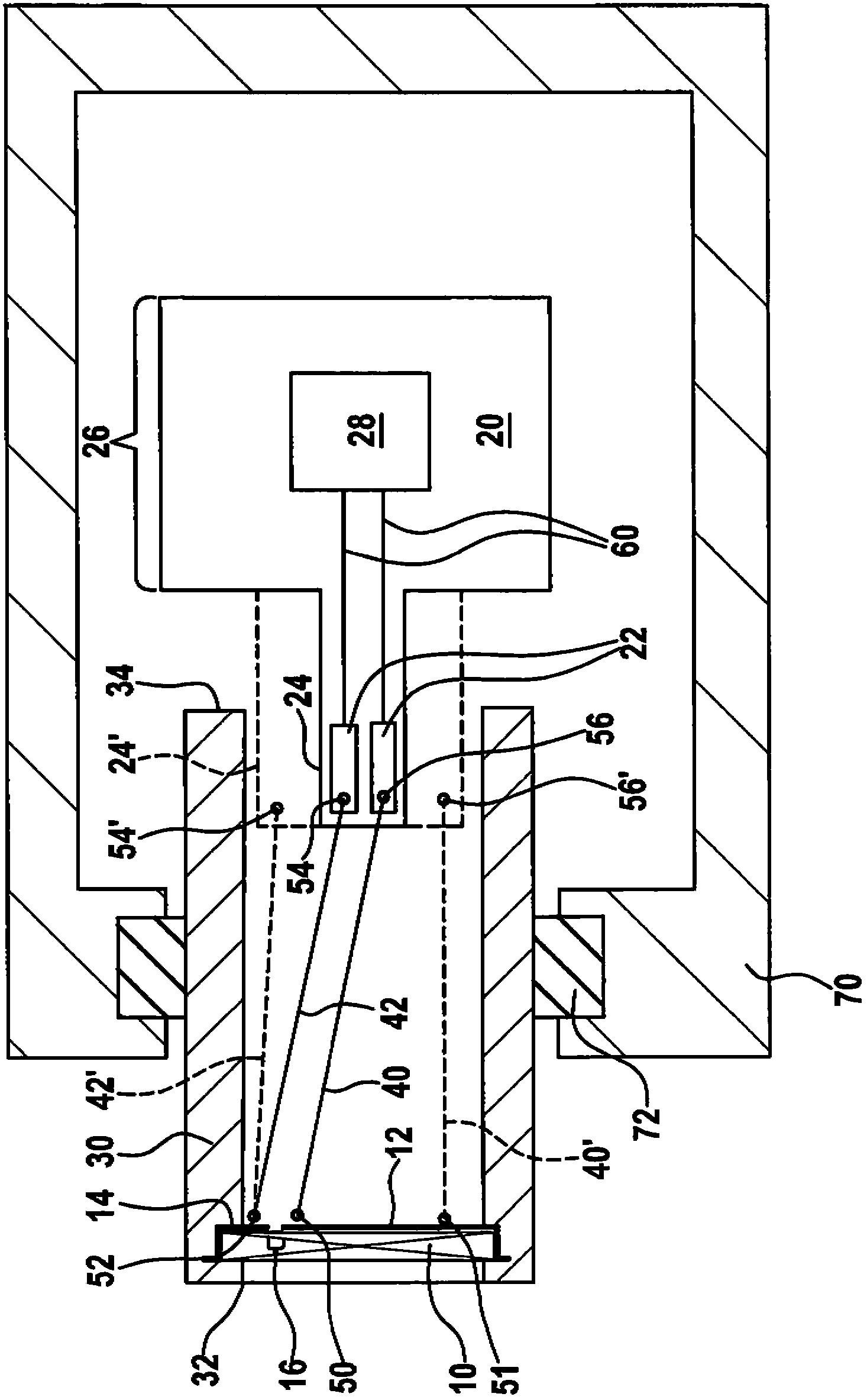
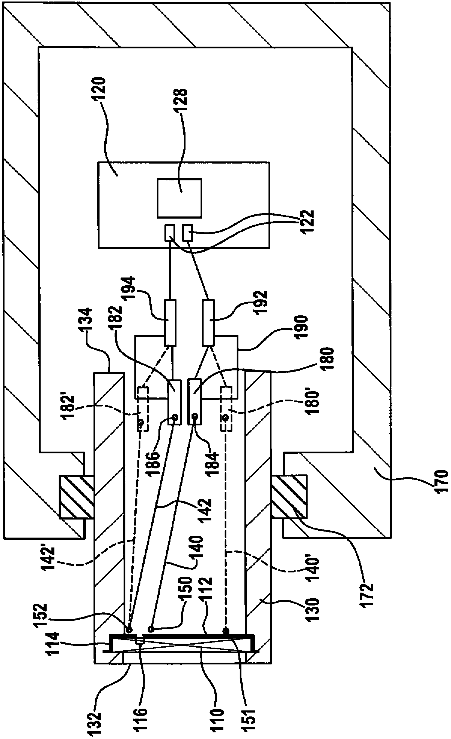
[0027] figure 1 An ultrasonic transducer according to the invention is shown with a piezoelectric element 10 , a printed circuit board 20 and a diaphragm disk 30 . The piezoelectric element 10 is bonded to the front end side 32 of the film disk 30 , preferably by means of a film, which forms a unit after bonding with the piezoelectric element 10 . The printed circuit board 20 carries two signal connections 22 , which are designed as planar conductors. The signal connection point 22 is arranged on a section 24 of the printed circuit board 22 protruding into the membrane tray 30 . Section 24 is designed as a protrusion of printed circuit board 20 . The piezoelectric element 10 is connected to the signal connection 22 via two lines 40 , 42 .

[0028] The piezoelectric element 10 comprises electrode surfaces 12 , 14 , between which an electrode gap with an electrode gap width 16 is formed. On the different electrode surfaces 12 , 14 of the piezo element 10 are formed contact p...


PUM


Abstract

The invention relates to an ultrasonic transducer, comprising a piezoelectric element, with a printed circuit board and with a diaphragm pot. The piezoelectric element is attached to the front face of the diaphragm pot and connected via at least two leads, to signal connection points of the printed circuit board. In one arrangement a portion of the circuit board projects into the diaphragm pot. The portion of the PCB may be smaller in width than the clear width of the diaphragm pot, and the remainder of the PCB may be arranged outside the pot. Alternatively the leads, (e.g. wires, single core cables) are arranged so that they run with a spacing from one another which is smaller than half the width of the piezoelectric element, preferably no more than the electrode gap width of the element. The transducer may be attached to a panel of a motor vehicle and used as a distance sensor. The distance sensor includes the ultrasonic transducer and also an acoustic damping ring and a housing. A maintaining cover of the ultrasonic transducer is connected with the housing through the damping ring. In addition, the invention relates to a method for manufacturing the ultrasonic transducer.

Description

Background technique [0001] It is known, in particular in automotive applications, to detect the distance to an object by means of the pulse-echo method. One procedure is to send scanning pulses with the aid of ultrasonic transducers, to receive the echoes and to perform distance calculations from the propagation time, with piezoelectric elements being used as transducer elements. [0002] Such ultrasonic transducers are installed in distance sensors in the vehicle housing in order to realize, for example, parking assistance or collision warning systems. [0003] Piezoelectric sensors are used in particular to receive ultrasound echoes, a voltage of a few millivolts being generated by the piezoelectric element. With such signal strengths, even small electromagnetic disturbances can significantly affect signal quality. [0004] Furthermore, connecting structures are known, for example in DE 102 61 033 A1, which are based on multi-core cables, but this entails complex steps in...

Claims


Application Information

Patent Timeline
IPC IPC(8): H04R17/00
CPCG10K9/22G01S7/521G01S15/931G10K11/004G10K9/122G01H11/08G01S7/52079
Inventor B·巴亚尔塞汉M·施耐德P·拉普斯T·S·舍费尔
Owner ROBERT BOSCH GMBH
Why Eureka
Try Eureka