LED constant-current control circuit and LED liquid crystal television
A constant current control circuit and constant current control technology, applied in the field of circuits, can solve problems such as difficult debugging, high price, and many components, and achieve the effects of reduced development difficulty, cheap price, and reduced use
- Summary
- Abstract
- Description
- Claims
- Application Information
AI Technical Summary
Problems solved by technology
Method used
Image

Examples
Embodiment 1
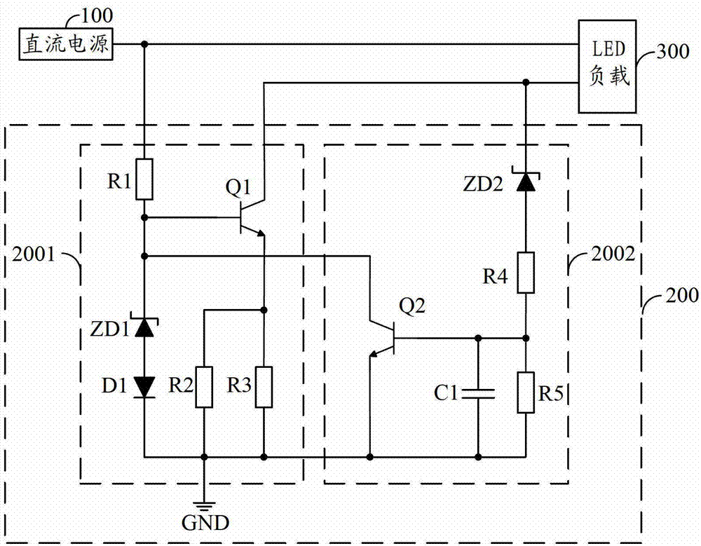
[0026] figure 2 The circuit structure of the LED constant current control circuit 200 provided by the first embodiment of the present invention is shown. For the convenience of description, only the parts related to the first embodiment of the present invention are shown, and the details are as follows:
[0027] As an embodiment of the present invention, the constant current control module 2001 includes: a voltage dividing resistor R1, a current limiting resistor R2, a current limiting resistor R3, a diode D11, a Zener diode ZD1 and an NPN transistor Q1.
[0028] The first terminal of the voltage dividing resistor R1 is the control terminal of the constant current control module 2001, the collector of the NPN transistor Q1 is the input terminal of the constant current control module 2001, the second terminal of the voltage dividing resistor R1 is connected to the base of the NPN transistor Q1 The base of the NPN transistor Q1 is the adjustment terminal of the constant current...
Embodiment 2
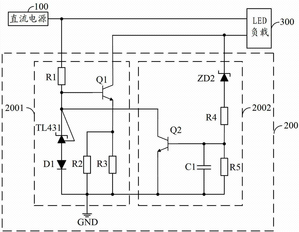
[0039] Figure 4 The circuit structure of the LED constant current control circuit 200 provided by the second embodiment of the present invention is shown. For the convenience of description, only the parts related to the second embodiment of the present invention are shown, and the details are as follows:
[0040] As an embodiment of the present invention, the constant current control module 2001 includes: a voltage dividing resistor R6, a current limiting resistor R7, a current limiting resistor R8, a diode D2, a Zener diode ZD3 and an N-type MOS transistor Q3;
[0041]The first end of the voltage dividing resistor R6 is the control end of the constant current control module 2001, the drain of the N-type MOS transistor Q3 is the input end of the constant current control module 2001, the second end of the voltage dividing resistor R6 is connected to the N-type MOS transistor Q3 The gates are connected, the gate of the N-type MOS transistor Q3 is the adjustment terminal of the...
PUM
 Abstract
Description
Claims
Application Information
 - R&D
- Intellectual Property
- Life Sciences
- Materials
- Tech Scout
- Unparalleled Data Quality
- Higher Quality Content
- 60% Fewer Hallucinations
Browse by: Latest US Patents, China's latest patents, Technical Efficacy Thesaurus, Application Domain, Technology Topic, Popular Technical Reports.
© 2025 PatSnap. All rights reserved.Legal|Privacy policy|Modern Slavery Act Transparency Statement|Sitemap|About US| Contact US: help@patsnap.com