Heat exchange device

A heat exchange device and heat exchanger technology, applied in heat exchange equipment, household heating, heating methods, etc., can solve the problems of unsatisfactory leveling requirements, obstacles, complicated connection operations, etc., and achieve the effect of easy assembly

Active Publication Date: 2012-12-19
SHARP KK
View PDF6 Cites 13 Cited by
  • Summary
  • Abstract
  • Description
  • Claims
  • Application Information

AI Technical Summary

Problems solved by technology

[0008] However, for two heat exchangers with different effective lengths, when the ventilation surfaces formed by the end edges of the plurality of cooling fins are opposed to and adjacent to each other, and the two are combined into one, due to the U-shaped connecting tube Welded to the ends of the refrigerant pipes that protrude from the mounting plates on the sides of the two heat exchangers, the connecting pipes become an obstacle and complicate the connection work between the mounting plates of the two heat exchangers
[0009] In Patent Document 1, in order to facilitate the assembly of the two heat exchangers, the two heat exchangers are installed and fixed at different heights, but this cannot meet the requirement of leveling the installation positions of the two heat exchangers on the side

Method used


Image

  • Heat exchange device
  • Heat exchange device
  • Heat exchange device

Examples


Embodiment Construction

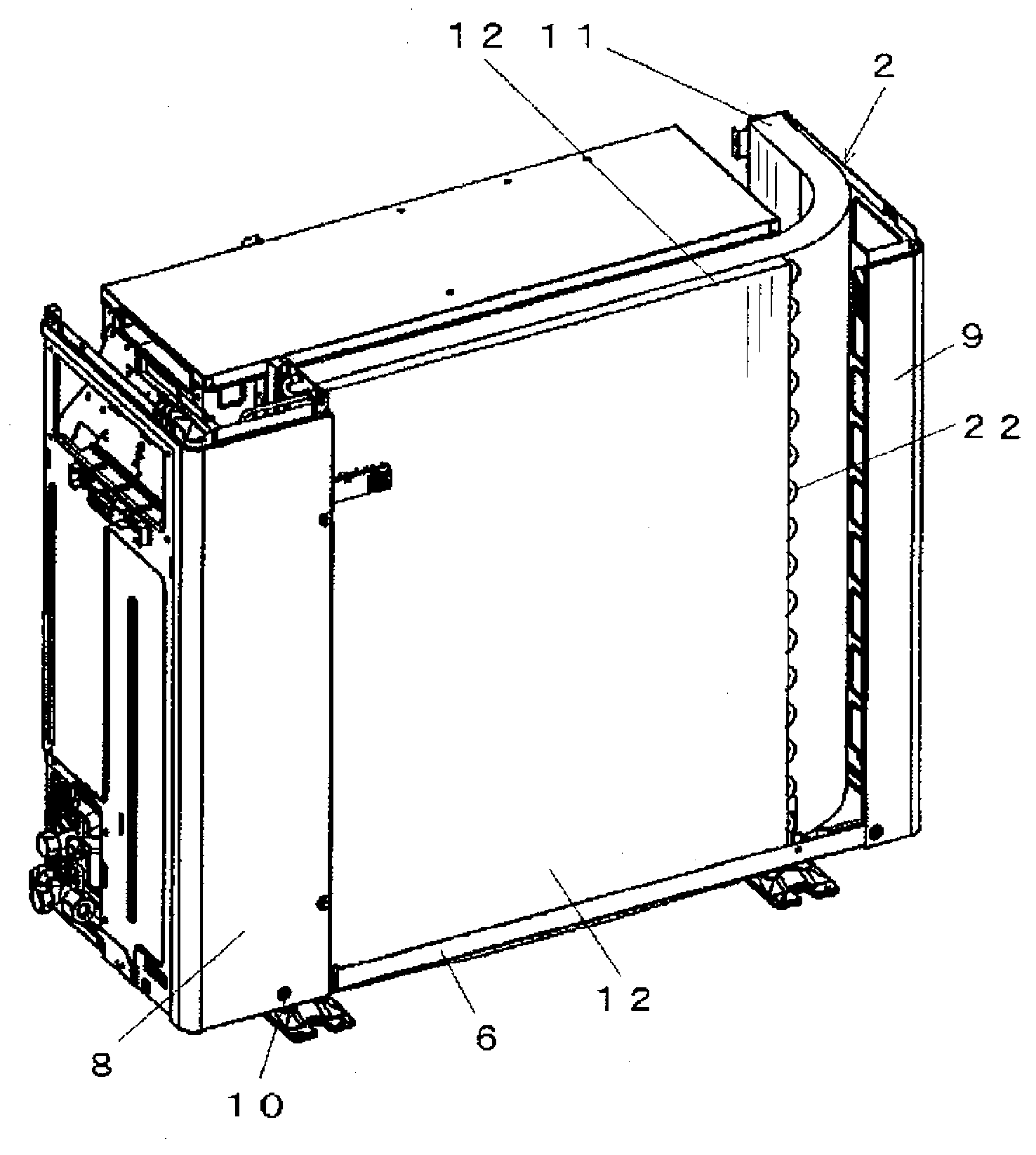
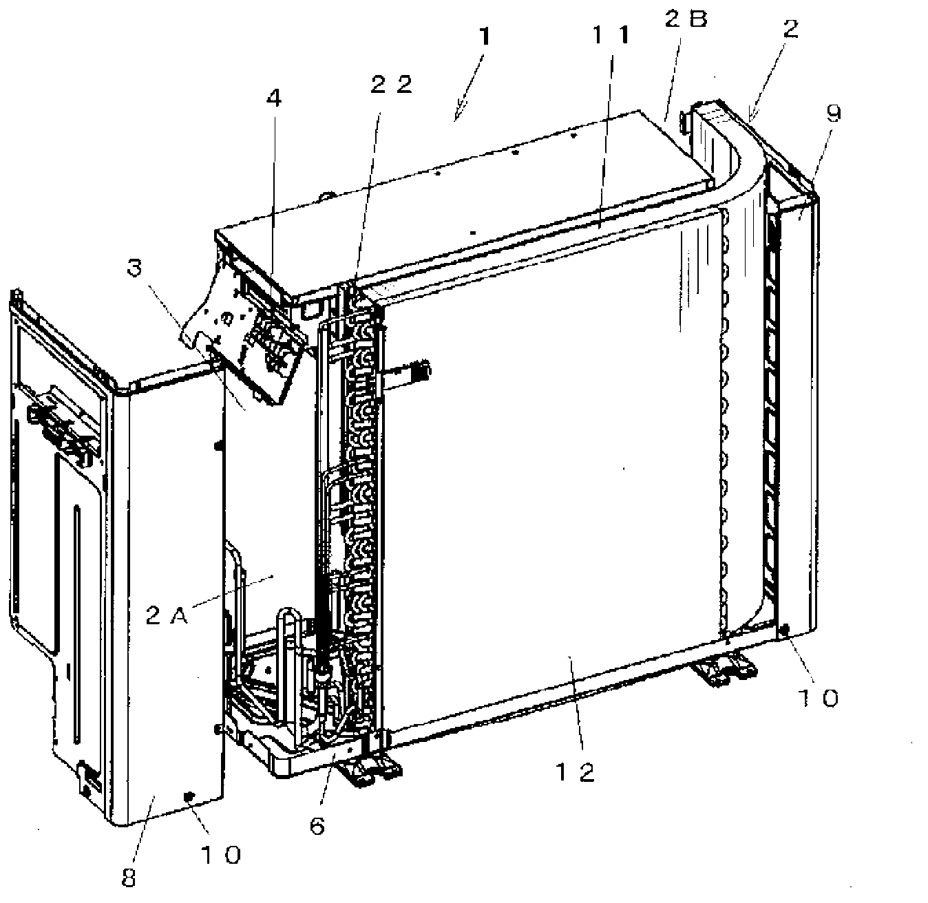
[0062] Embodiments in which the heat exchange device of the present invention is applied to an outdoor unit of an air conditioner will be described with reference to the drawings. Such as figure 1 and figure 2 As shown, the outdoor unit of the air conditioner has a housing 2 constituting the outer shell of the outdoor unit 1, and the interior of the housing 2 is divided into a compressor room 2A with a compressor (not shown) and electronic components 4 built in through a partition 3. And the heat exchanger chamber 2B in which the heat exchange device 5 and the air blower (not shown) arrange|positioned facing the heat exchange device 5 are built. The compressor and the heat exchange device 5 are components of a refrigeration cycle, and are connected by refrigerant pipes (not shown).

[0063] The casing 2 is formed into a box shape by a bottom plate 6 , an upper panel (not shown), a front panel (not shown), a rear panel (not shown), and left and right side panels (right side ...


PUM


Abstract

Provided is a heat exchange device wherein work for assembling a plurality of heat exchangers can be easily performed. A first heat exchanger (11) and a second heat exchanger (12) are disposed close to each other with the ventilation surfaces thereof facing each other, and a first mounting plate (13) affixed to a side surface of the first heat exchanger and a second mounting plate (14) affixed to a side surface of the second heat exchanger are joined and affixed to each other while facing each other. In this case, the first mounting plate (13) has a space of a size capable of connecting and affixing the second mounting plate (14) thereto while both the plates facing each other, multiple stages of insertion holes (25) into which pipe ends of multiple stages of refrigerant pipes (16) projecting laterally to the space from the second mounting plate (14) are inserted are formed, the insertion hole (25) is formed larger than the pipe diameter of the end of the refrigerant pipe (16), and a guide wall (26) for guiding the end of the refrigerant pipe of the second heat exchanger to a predetermined position is formed in each of at least some insertion holes (25) among the multiple stages of insertion holes (25).

Description

technical field [0001] The present invention relates to a heat exchange device used in an air conditioner. Background technique [0002] As a heat exchange device used in such an air conditioner, Patent Document 1 discloses a device having a first heat exchanger disposed opposite to and adjacent to each other and a second heat exchanger having a shorter effective length than the first heat exchanger. The side of the first heat exchanger is provided with an L-shaped first mounting plate bent on the ventilation surface of the front side or the back side of the heat sink, and the side of the same side of the second heat exchanger is On the top, there is an L-shaped second mounting plate whose first heat exchanger side is bent toward the protruding direction of the refrigerant pipe. The engaging holes and the locking claws of the second heat exchanger are positioned at positions different in height from the sides of the first heat exchanger. [0003] In addition, Patent Docume...

Claims


Application Information

Patent Timeline
Patent Type & Authority Applications(China)
IPC IPC(8): F24F1/16F28F9/02
CPCF28D1/0477F28F9/001F24F1/16F24F13/30F28D1/0435Y10T29/4935F28D1/0443F28D1/0452F28F2009/004
Inventor 绞野佳延
Owner SHARP KK
Why Eureka
Try Eureka