Air total heat exchanger for changing runner to improve efficiency

A technology of total heat exchanger and total heat exchange core, applied in the field of air total heat exchanger, can solve the problems of localized air distribution concentration, thinness, and affecting the heat exchange efficiency of total heat exchanger

Active Publication Date: 2012-12-26
SHANGHAI INST OF CERAMIC CHEM & TECH CHINESE ACAD OF SCI
View PDF7 Cites 21 Cited by
  • Summary
  • Abstract
  • Description
  • Claims
  • Application Information

AI Technical Summary

Problems solved by technology

Adopting this air intake method improves the problem of uneven distribution of exhaust air and fresh air after entering the core of the total heat exchanger to a certain extent. However, there are still local air distribution problems that are too concentrated or thin along the direction of the core. Phenomenon
[0007] At the same time, when using the total heat exchangers described in Patent Document 1 and Patent Document 2, due to the design of multiple corners in the channel design, it is easy to generate eddy currents locally when the air passes through the channels, which affects the thermal efficiency of the total heat exchanger. Exchange efficiency, while increasing the pressure loss of the entire heat exchange process

Method used


Image

  • Air total heat exchanger for changing runner to improve efficiency
  • Air total heat exchanger for changing runner to improve efficiency
  • Air total heat exchanger for changing runner to improve efficiency

Examples


Embodiment Construction

[0074] The present invention will be described in further detail below in conjunction with the embodiments and accompanying drawings. It should be noted that the content of the present invention is not limited to these specific embodiments. On the premise of not departing from the background and spirit of the present invention, those skilled in the art can make equivalent replacements and modifications on the basis of reading the content of the present invention, and the content is also included in the scope of protection of the present invention.

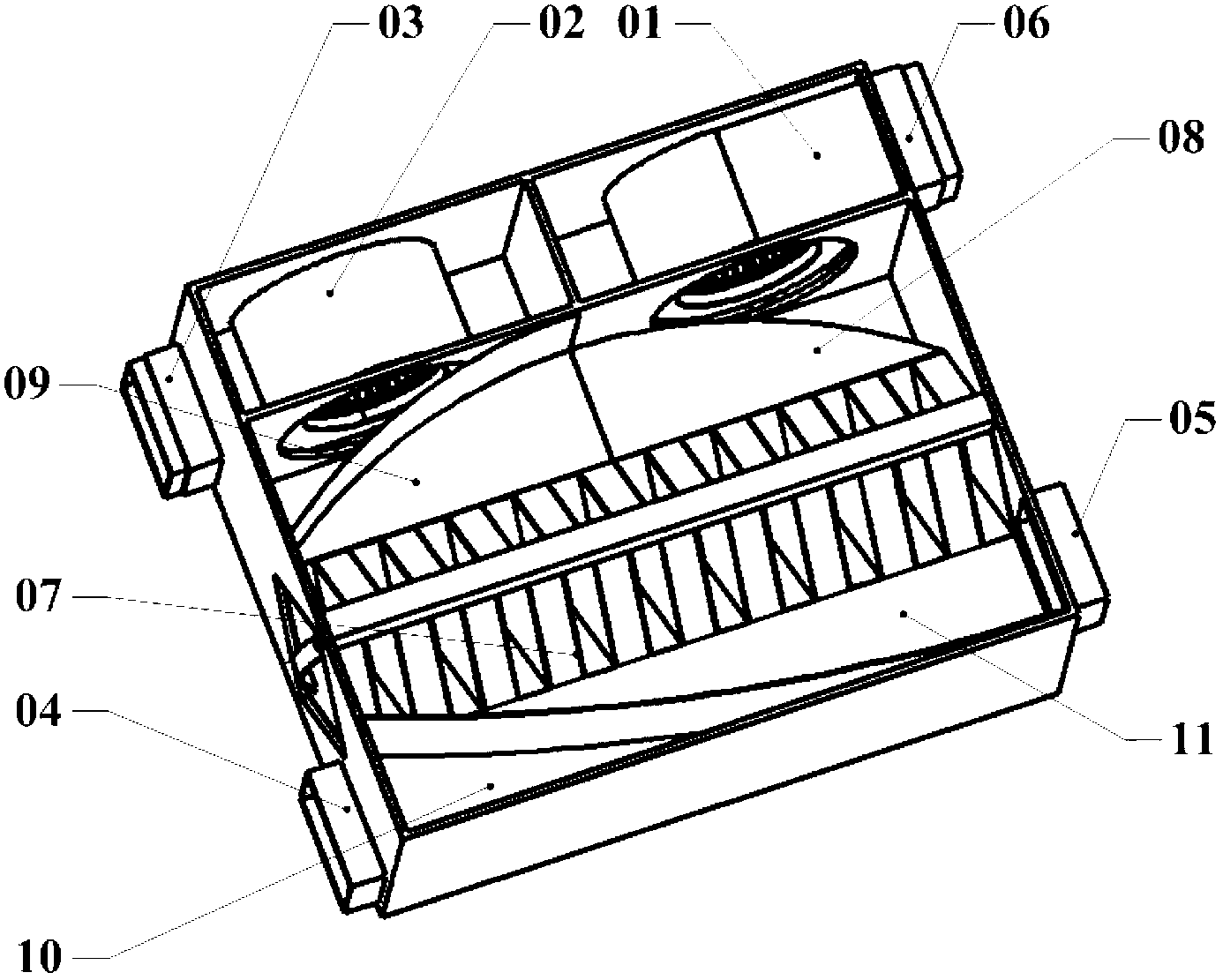
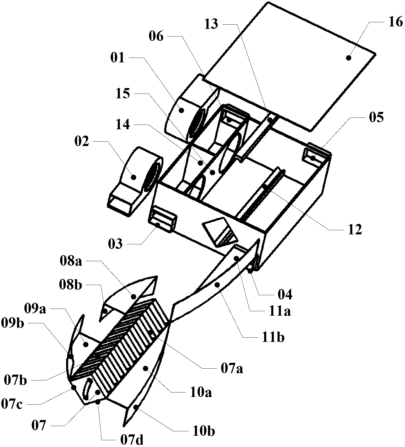
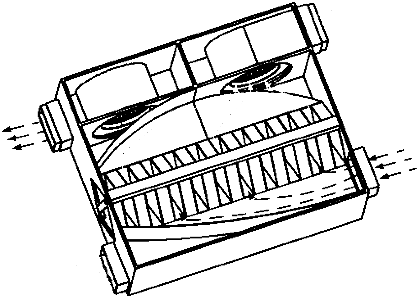
[0075] Such as figure 1 , as shown in 2, the total heat exchanger can be divided into three parts: the fresh air flow path, the exhaust air flow path and the heat exchange core according to the different flow paths:

[0076] 1. The fresh air passage of the total heat exchanger consists of fresh air inlet 04, fresh air outlet horizontal partition 09a, fresh air outlet side diversion partition 09b, fresh air inlet horizontal partiti...


PUM


Abstract

The invention relates to a novel air total heat exchanger which comprises a fresh air runner, a fresh air fan, an exhaust air runner, an exhaust fan and a total heat exchange core body. Fresh air and exhaust air are subjected to total heat exchange through a heat-moisture exchange membrane in the total heat exchange core body; inlets and outlets of the fresh air and the exhaust air of the total heat exchanger are laterally arranged relative to the total heat exchange core body; the fresh air inlet and the exhaust air outlet are arranged at the same end faces of different sides on the same horizontal plane; the fresh air outlet and the exhaust air inlet are arranged at the same end faces of the different sides on the same horizontal plane; the fresh air inlet and the exhaust air outlet are respectively arranged at the upper and lower layers (or lower and upper layers) at the same side of the total heat exchange core body; the fresh air outlet and the exhaust air inlet are respectively arranged at the lower and upper layers (or upper and lower layers) at the other same side of the total heat exchange core body, and diversion partition plates are arranged inside the fresh air runner and the exhaust air runner. Therefore, the air can be uniformly arranged on the total heat exchange core body; the total heat exchange efficiency is improved, and the air resistance is reduced.

Description

technical field [0001] The invention relates to a device for exchanging total heat (including sensible heat and latent heat) of indoor and outdoor air. More particularly, the present invention relates to an air total heat exchanger with an improved channel structure, which can improve total heat exchange efficiency and reduce resistance. Background technique [0002] In order to ensure that the indoor air is fresh, sufficient fresh air volume must be ensured in the building air conditioner. Especially due to the rapid development of chemical industry and material industry, a large amount of artificial synthetic materials have appeared as building materials and decoration materials, and these materials can release harmful gases such as formaldehyde, benzene, toluene, ethanol, chloroform, etc. The deterioration of the indoor air environment causes people in the building to feel uncomfortable, dizzy, irritated, nauseous and even sick, which has triggered the following three di...

Claims


Application Information

Patent Timeline
Patent Type & Authority Applications(China)
IPC IPC(8): F24F13/30
Inventor 杨莉萍钟秋
Owner SHANGHAI INST OF CERAMIC CHEM & TECH CHINESE ACAD OF SCI
Why Eureka
Try Eureka