Public voltage compensation circuit and method, and liquid crystal display device
A common voltage and compensation method technology, applied in the direction of adjusting electrical variables, static indicators, instruments, etc., can solve the problems of reducing circuit accuracy, affecting the display effect, and inability to compensate and adjust the common voltage, so as to achieve signal interference suppression and accurate compensation. The effect of high degree and improved display effect
- Summary
- Abstract
- Description
- Claims
- Application Information
AI Technical Summary
Problems solved by technology
Method used
Image
Examples
Embodiment 1
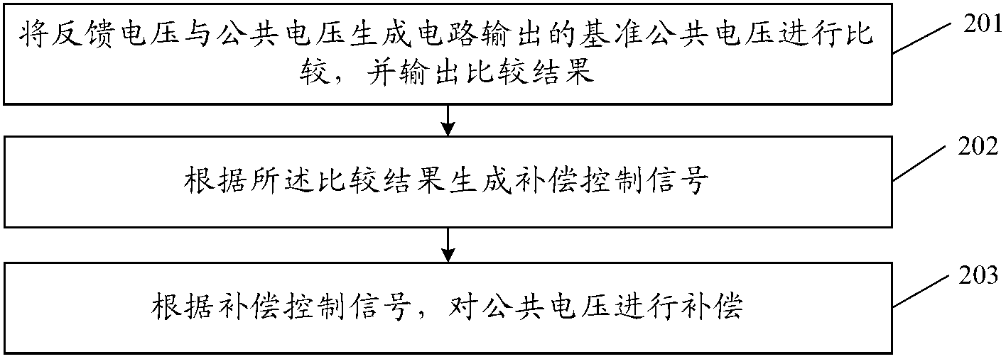
[0048] An embodiment of the present invention provides a common voltage compensation method, such as figure 2 As shown, the common voltage compensation method includes:
[0049] Step 201, compare the feedback signal with the reference common voltage value Vref output by the common voltage generating circuit, and output the comparison result, the feedback signal is the common voltage actually obtained by the common electrode;
[0050] The liquid crystal display device includes: a liquid crystal panel and a common voltage generating circuit, the liquid crystal panel is provided with a common electrode, one end of the common electrode is connected to the common voltage generating circuit as an input end, and the other end of the common electrode is used as a feedback end, and the actual voltage of the common electrode is output. The obtained common voltage is used as a feedback voltage for controlling compensation. Comparing the feedback voltage (that is, the common voltage act...
Embodiment 2
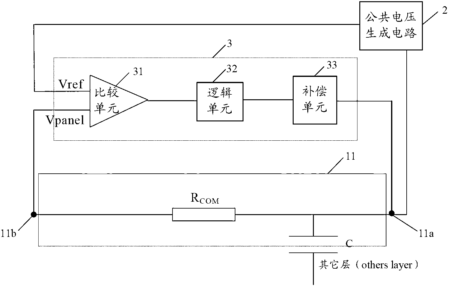
[0060] A schematic structural diagram of a common voltage compensation circuit provided by an embodiment of the present invention, as shown in image 3 As shown, the common voltage compensation circuit 3 is provided with two input terminals and an output terminal, the input terminals are respectively connected to the common voltage generation circuit 2 and the common electrode 11 arranged on the liquid crystal panel, and the output terminal is also connected to the common electrode 11 , the common voltage compensation circuit 3 includes:
[0061] The comparison unit 31 is configured to receive the feedback voltage Vpanel and the reference common voltage Vref output by the common voltage generating circuit 2, compare the feedback voltage Vpanel with the reference common voltage Vref, and output the comparison result, the feedback voltage Vpanel is actually obtained on the common electrode 11 public voltage;
[0062] The logic unit 32 generates a compensation control signal acc...
specific Embodiment 3
[0080] Such as Figure 6 As shown, it is the third specific embodiment of the compensation unit of the public voltage compensation circuit of the present invention, and the compensation unit 33 includes:
[0081] N-type field effect transistor and P-type field effect transistor form a complementary symmetrical structure;
[0082] The gates of the N-type field effect transistor and the P-type field effect transistor are all connected to the logic unit 32, the source (input terminal) of the N-type field effect transistor inputs the first level signal V1, and the source of the P-type field effect transistor The second level signal V2 is input, and the drains (output terminals) of the N-type field effect transistor and the P-type field effect transistor are connected to the common electrode.
[0083] Wherein, the compensation control signal output by the logic unit 32 is any one of the first control signal, the second control signal and the third control signal. The voltage of t...
PUM
 Abstract
Description
Claims
Application Information
 - R&D
- Intellectual Property
- Life Sciences
- Materials
- Tech Scout
- Unparalleled Data Quality
- Higher Quality Content
- 60% Fewer Hallucinations
Browse by: Latest US Patents, China's latest patents, Technical Efficacy Thesaurus, Application Domain, Technology Topic, Popular Technical Reports.
© 2025 PatSnap. All rights reserved.Legal|Privacy policy|Modern Slavery Act Transparency Statement|Sitemap|About US| Contact US: help@patsnap.com


