
Electrode including magnetic material and organic light emitting device including the electrode

A technology of organic light-emitting devices and magnetic materials, applied in circuits, electrical components, electric solid devices, etc., can solve the problems of difficult charge injection and lower hole injection efficiency, and achieve the effect of increasing light emission efficiency and good charge injection characteristics

Inactive Publication Date: 2012-12-26
SAMSUNG DISPLAY CO LTD
View PDF7 Cites 6 Cited by
  • Summary
  • Abstract
  • Description
  • Claims
  • Application Information

AI Technical Summary

Problems solved by technology

However, if a metal layer is used as an electrode in this way, it may be difficult to inject charges
In particular, when a reflective electrode including a metal layer is used as an anode, the efficiency of hole injection is reduced

Method used


Image

  • Electrode including magnetic material and organic light emitting device including the electrode
  • Electrode including magnetic material and organic light emitting device including the electrode
  • Electrode including magnetic material and organic light emitting device including the electrode

Examples


Embodiment approach

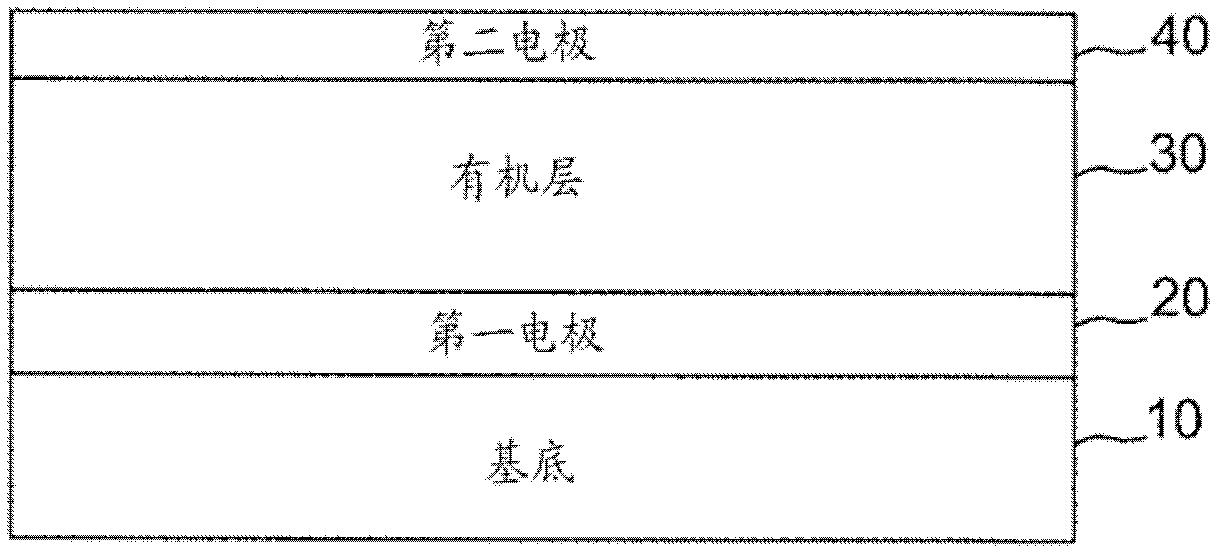
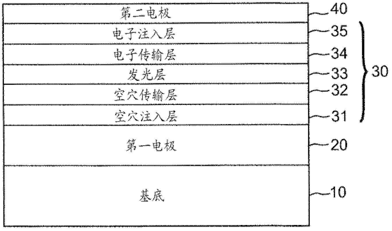
[0078] In this regard, according to an exemplary embodiment of the present invention, magnetic materials included in the electrodes have the same magnetization direction (or rotation direction). When the magnetic material included in the electrodes is magnetized in the same direction, only charges having a rotation direction corresponding to the magnetization direction can be injected into the light emitting layer. By using the electrode including the magnetic material, the present invention can control the rotation direction of charges injected into the light emitting layer, thereby possibly improving the light emission efficiency of the organic light emitting device.

[0079] In particular, when the magnetization direction of the magnetic material included in the electrode, that is, the rotation direction is an upward direction, charges with an upward rotation direction pass through the electrode without being blocked, but charges with a downward rotation direction are blocke...


PUM


Abstract

An electrode, which includes a magnetic material to improve the flow of charges, and an organic light emitting device using the electrode. The electrode for the organic light emitting device has an excellent charge injection property, so that it is possible to improve the efficiency of light emission of the organic light emitting device.

Description

[0001] priority claim [0002] This application requires June 22, 2011 filed at the Korean Intellectual Property Office 10-2011-0060794 Priority and benefits of Korean Patent Application No. technical field [0003] The present invention relates to an electrode comprising a magnetic material to enhance charge flow, and an organic light emitting device using the same. Background technique [0004] Electroluminescent devices, especially organic light emitting devices, which have recently taken a prominent place in the field of displays, are devices that utilize the recombination and dissipation of electrons and holes to generate light and emit light. [0005] The electroluminescent device basically includes an electrode for injecting holes, an electrode for injecting electrons, and a light-emitting layer, and the electroluminescent device has a laminated structure in which the light-emitting layer is layered on the electrode for injecting holes and the electrodes used to in...

Claims


Application Information

Patent Timeline
Patent Type & Authority Applications(China)
IPC IPC(8): H01L51/52H01L51/56
CPCH01L51/5218H10K50/818H05B33/26H01L2933/0016H10K2102/301
Inventor 李濬九金元锺郑知泳崔镇百李娟和李昌浩吴一洙宋炯俊尹振渶宋英宇李钟赫
Owner SAMSUNG DISPLAY CO LTD
Learn More