
Excitation response simulation circuit applied to printer

An excitation-response, analog circuit technology, applied in printing, electrical components, power oscillators, etc., can solve the problems of poor compatibility of excitation-response analog circuits, easy ink leakage, and high manufacturing costs, and improve the characteristics of positive and negative polarity circuits. , improve the DC characteristics, and facilitate the effect of integration

Active Publication Date: 2015-04-15
APEX MICROELECTRONICS CO LTD
View PDF4 Cites 0 Cited by
  • Summary
  • Abstract
  • Description
  • Claims
  • Application Information

AI Technical Summary

Problems solved by technology

[0010] There are disadvantages in the judgment of whether the remaining amount of ink in the ink cartridge is full: first, the cost of the cavity material used in the piezoelectric ceramic module and the manufacturing involved The cost is high; second, the cavity used by the piezoelectric ceramic should be set in the ink cartridge, which has poor sealing performance, and the ink in the ink cartridge is easy to leak; third, the cavity used by the piezoelectric ceramic Long-term immersion in ink, easy to corrode
However, if the excitation signals added to both ends of the circuit by the inkjet printer are high-level signals, such as the signals added to the two ends are respectively 4 volts and 40 volts, then the positive and negative polarity circuits with the reference potential being GND It is not possible to make circuits with different impedances and time constants that meet the requirements of inkjet printers
Therefore, the compatibility of current stimulus-response analog circuits is relatively poor, and the applicable types of inkjet printers are limited.

Method used


Image

  • Excitation response simulation circuit applied to printer
  • Excitation response simulation circuit applied to printer
  • Excitation response simulation circuit applied to printer

Examples


Embodiment Construction

[0056] In order to make the object, technical solution and advantages of the present invention clearer, the present invention will be further described in detail below with reference to the accompanying drawings and examples.

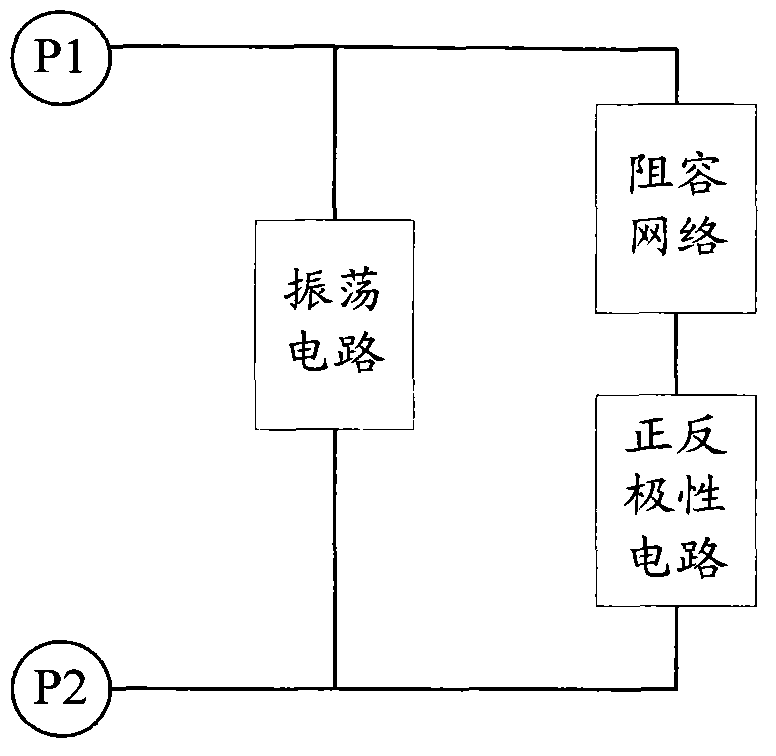
[0057] Figure 7 A schematic diagram of an excitation response analog circuit applied to a printer provided by the present invention, the positive and negative polarity circuits in this structure are implemented by an insulated gate field effect transistor and a resistance-capacitance adjustment module. Specifically, and prior art Figure 5 Compared with the stimulus-response analog circuit in the above, the forward and reverse polarity circuit adopts N-type insulated gate field effect transistor Q2 to connect resistor R1 and capacitor C1 in series to realize, wherein, the gate of N-type insulated gate field effect transistor Q2 The pole is connected to an excited end of the circuit, the source is connected in series with the resistor R1, the drain is ...


PUM


Abstract

The invention discloses an excitation response simulation circuit applied to a printer. A positive and negative pole circuit of the traditional excitation response simulation circuit comprises an insulated grid field effect transistor. According to the invention, an electric level control module is also additionally arranged in the traditional excitation response simulation circuit and is used for providing reference potential for the positive and negative pole circuit in the excitation response simulation circuit, namely, voltages close to excitation signals, which are added to two ends of the excitation response simulation circuit by an inkjet printer, are used as the reference potential. Therefore, the excitation response simulation circuit on the printer, provided by the invention, has the capability of simulating the excitation response matched with the inkjet printer on the basis of improving the characteristic of the positive and negative pole circuit.

Description

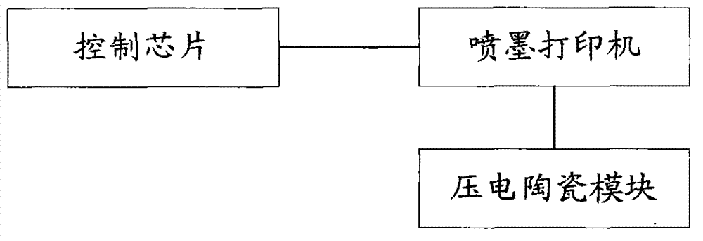
[0001] (This application is a divisional application of an invention patent application with an application date of August 13, 2010, an application number of 201010254668.0, and an invention title of "Stimulus Response Simulation Circuit and Stimulus Response Simulation Method Applied to Printers".) technical field [0002] The invention relates to the field of printers, in particular to an excitation-response analog circuit applied to a printer. Background technique [0003] The control part of the inkjet printer is mainly composed of the control chip and the inkjet printer, such as figure 1 As shown, the control chip is generally bound to the ink cartridge, and its function is to control the matching of the ink cartridge and the inkjet printer and the provision of printing information during the subsequent printing process. In the control chip, initial information such as the ink cartridge model, color, and total amount of ink is recorded. And printing information such as ...

Claims


Application Information

Patent Timeline
Patent Type & Authority Patents(China)
IPC IPC(8): H03B5/12B41J2/175
Inventor 丁励
Owner APEX MICROELECTRONICS CO LTD
Learn More