
Wedge-shaped carrier for solar cells

A technology of solar cells and wedge-shaped supports, which is applied in the field of photovoltaic systems, can solve the problems of forming gaps, etc., and achieve the effect of rapid installation and maintenance, and simple installation and maintenance

Inactive Publication Date: 2012-12-26
SIKA TECH AG
View PDF6 Cites 0 Cited by
  • Summary
  • Abstract
  • Description
  • Claims
  • Application Information

AI Technical Summary

Problems solved by technology

The disadvantage of this type of fastening is, however, that the solar cells, in particular, can separate from the roof sheet due to mechanical stress and gaps can form between them
Also, the installed solar cells are difficult to remove from the roof sheeting, which is a disadvantage in repair situations

Method used


Image

  • Wedge-shaped carrier for solar cells
  • Wedge-shaped carrier for solar cells
  • Wedge-shaped carrier for solar cells

Examples


Embodiment Construction

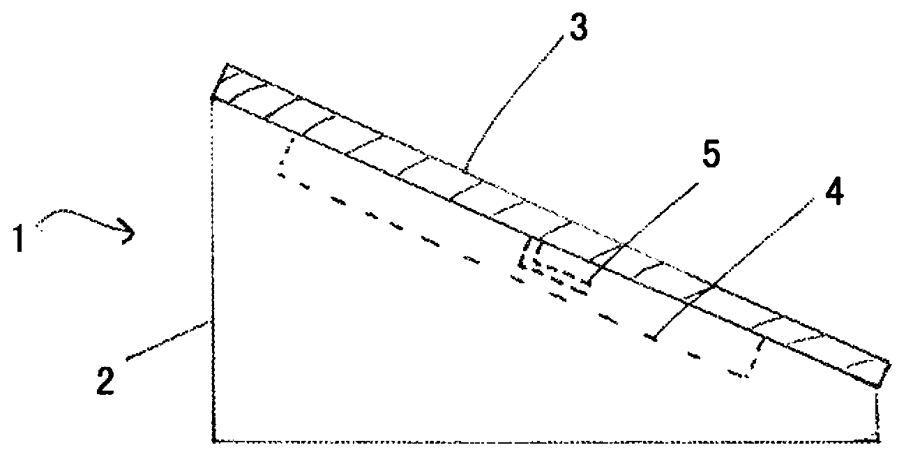
[0028] figure 1 A photovoltaic system 1 is shown comprising a wedge-shaped support 2 and at least one solar cell 3 , which comprises a cutout 4 for an electrical connection 5 of the at least one solar cell.

[0029] The term "wedge" in the context of the present invention refers to an object whose two sides meet at an acute angle, especially at an angle between 3°-45°, preferably 3°-30°, particularly preferably 3°-20°, One of the sides is oriented towards the solar cell and the other is oriented towards the base.

[0030] The term "solar cell" in the context of the present invention refers both to a single solar cell and to a plurality of solar cells that are electrically and / or mechanically connected to one another. Such solar cells are marketed, for example, by the German company BP Solar or the German company Sharp Solar.

[0031] The solar cells usually have a frame made of glass or metal and are usually enclosed in a plastic layer which protects them from moisture damag...


PUM


Abstract

In a photovoltaic system (1) comprising a wedge-shaped carrier (2) and at least one solar cell (3), the photovoltaic system has an intermediate space (4) for means for electrically connecting (5) the at least one solar cell (3).

Description

technical field [0001] The invention relates to a photovoltaic system comprising a wedge-shaped support and at least one solar cell according to the preamble of claim 1 . Background technique [0002] It is known to mount solar cells on roofing sheets by means of adhesives. However, this type of fastening has the disadvantage that, in particular, the solar cells can separate from the roofing sheet due to mechanical stress and gaps can form between them. Moisture that then penetrates into the air gap has a particularly adverse effect on the connection of solar cells and roofing sheets, in particular by damaging the adhesive, and aggravates the separation. In addition this type of fixing is not suitable for uneven bases. [0003] Furthermore, the adhesive is exposed to external influences, such as weather or UV rays, which leads to damage of the adhesive over time by external influences, whereby the connection is further weakened. [0004] Another problem is that the solar ...

Claims


Application Information

Patent Timeline
Patent Type & Authority Applications(China)
IPC IPC(8): H01L31/048F24J2/52
CPCY02B10/20H01L31/0483F24J2002/5284F24J2002/4676F24J2/5237F24J2002/467F24J2002/4689Y02E10/50H01L31/0482Y02B10/12F24J2/5262Y02E10/47H02S20/23H02S20/25F24S2080/013F24S2025/016F24S2025/601F24S2025/6007F24S25/11F24S25/67Y02B10/10
Inventor A·布莱布勒H·迈尔H·罗雷尔
Owner SIKA TECH AG
Learn More