Supercharge Your Innovation With Domain-Expert AI Agents!

Locating structure for linear motor of PCB (Printed Circuit Board) drilling machine

A technology of linear motor and positioning structure, which is applied to drilling/drilling equipment, large fixed members, components of boring machine/drilling machine, etc. Reduce the effect of part deformation

Active Publication Date: 2013-01-02
SUZHOU VEGA TECH CO LTD
View PDF3 Cites 2 Cited by
  • Summary
  • Abstract
  • Description
  • Claims
  • Application Information

AI Technical Summary

Problems solved by technology

The disadvantage of this structure is that it increases the cost of two linear guide rails

Method used


Image

  • Locating structure for linear motor of PCB (Printed Circuit Board) drilling machine
  • Locating structure for linear motor of PCB (Printed Circuit Board) drilling machine
  • Locating structure for linear motor of PCB (Printed Circuit Board) drilling machine

Examples


Embodiment 1

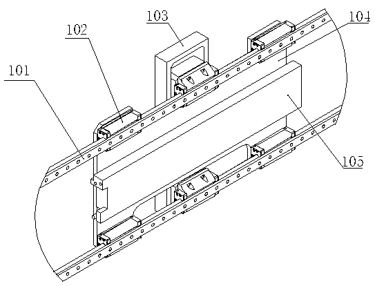
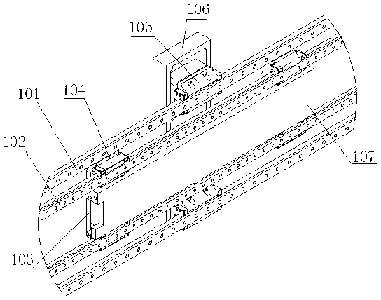
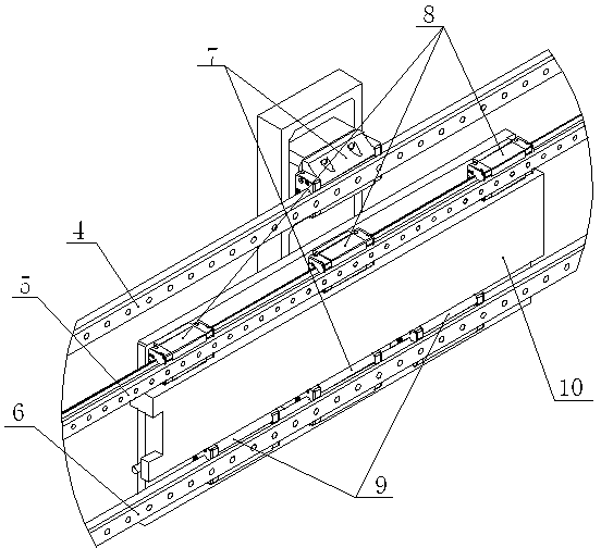
[0023] Such as image 3 and Figure 4 As mentioned above, the linear guide rail 4 of the base plate, the linear guide rail 5 of the fixed plate, and the shared linear guide rail 6 are respectively fixed on the marble beam, and the Z-axis base plate 2 is respectively connected to the linear guide rail 4 of the base plate and the shared linear guide rail 6 through two sliders 7. Swipe left and right. The linear motor 10 is connected on the motor fixing plate 1 by screws, and the motor fixing plate 1 is respectively connected to the fixing plate linear guide rail 5 and the shared linear guide rail 6 through three sliders 8 and two sliders 9 to realize left and right sliding. The motor fixing plate 1 and the Z-axis bottom plate 2 are connected through two X-axis connecting blocks 3 to realize power transmission. The motor fixing plate 1 and the Z-axis bottom plate 2 share a common linear guide rail 6 at one end, which can reduce the deformation of parts caused by the suction for...

Embodiment 2

[0025] The rest are the same as in Embodiment 1, except that the motor fixing plate 1 is respectively connected to the fixing plate linear guide rail 5 and the common linear guide rail 6 through four sliders 8 and four sliders 9 to realize left and right sliding. The size of the motor fixing plate 1 is set according to the size of the linear motor 10 , and the number of sliders is set according to the size of the motor fixing plate 1 .

Embodiment 3

[0027] The rest is the same as that of Embodiment 1, except that the motor fixing plate 1 and the Z-axis bottom plate 2 are connected through four X-axis connecting blocks 3 to realize power transmission. According to the different sizes of the motor fixing plate 1 and the Z-axis base plate 2 , the number of X-axis connecting blocks 3 can be set to effectively connect the motor fixing plate 1 and the Z-axis base plate 2 .


PUM


Abstract

The invention discloses a locating structure for a linear motor of a PCB (Printed Circuit Board) drilling machine. The locating structure is characterized by comprising a motor fixing plate, a Z-axis bottom plate, an X-axis connection block, linear guide rails, sliding blocks and the linear motor; the sliding blocks are respectively arranged at the two ends of the motor fixing plate and at the two ends of the Z-axis bottom plate; the linear guide rail comprises a fixing plate linear guide rail, a bottom plate linear guide rail and a common linear guide rail; the sliding blocks at one end of the motor fixing plate and at one end of the Z-axis bottom plate are respectively arranged on the fixing plate linear guide rail and the bottom plate linear guide rail, and the sliding blocks at the other end of the motor fixing plate and at the other end of the Z-axis bottom plate are respectively arranged the common linear guide rail; the linear motor is arranged on the motor fixing plate; and the motor fixing plate is connected with the Z-axis bottom plate through the X-axis connection block. According to the technical scheme, the locating structure for the linear motor of the PCB (Printed Circuit Board) drilling machine disclosed by the invention has the beneficial effects of effectively reducing the deformation of parts caused by the suction of the linear motor, ensuring machining precision, reducing equipment cost, and being simple in structure.

Description

technical field [0001] The invention relates to a PCB drilling machine, in particular to a linear motor positioning structure of the PCB drilling machine. Background technique [0002] There are mainly two traditional positioning methods for the X-axis linear motor of PCB drilling machine: [0003] Such as figure 1 As shown, the linear motor 105 is fixed on the motor fixing plate 104, and then connected to the linear guide rail 101 through the slider 102, as figure 1 shown. The disadvantage of this structure is that the motor fixing plate 104 and the Z-axis base plate 103 share two linear guide rails 101. Since the Z-axis movement stroke determines the length of the Z-axis base plate, the distance between the two linear guide rails will be too large. The linear motor 105 is installed in the middle of the linear guide rail 101 through the motor fixing plate 104. Due to the strong suction between the linear motor mover and the stator, the motor fixing plate 104 and the Z-ax...

Claims


Application Information

Patent Timeline
Patent Type & Authority Applications(China)
IPC IPC(8): B23B47/00B23Q1/01
Inventor 常远邱四军冯忠俊罗志建
Owner SUZHOU VEGA TECH CO LTD
Features
  • R&D
  • Intellectual Property
  • Life Sciences
  • Materials
  • Tech Scout
  • Unparalleled Data Quality
  • Higher Quality Content
  • 60% Fewer Hallucinations
Learn More