
Composite pile foundation structure

A foundation structure and composite pile technology, which is applied in the field of foundation structure and pile foundation, can solve the problems of single pile foundation diameter, wall thickness, penetration depth increase, complex structure and construction technology, and difficulty in offshore piling construction, etc., to achieve anti-vertical Increased load and bending moment capacity, reduced material cost, and reduced pile length

Inactive Publication Date: 2013-01-02
TIANJIN UNIV
View PDF9 Cites 8 Cited by
  • Summary
  • Abstract
  • Description
  • Claims
  • Application Information

AI Technical Summary

Problems solved by technology

However, due to the weaknesses of the single pile foundation such as poor anti-overturning ability and large horizontal displacement, as the single unit capacity of offshore wind turbines increases to 3MW, 5MW or more, the diameter, wall thickness and penetration depth of the single pile foundation will inevitably increase sharply. Large, resulting in difficulties in offshore piling construction and a substantial increase in construction costs
[0004] Three-pile tripods, multi-pile jackets, and high-pile cap foundations can effectively disperse loads and improve overturning resistance through different methods, but their structures and construction processes are complex and require high sea conditions, resulting in long construction periods and high construction costs.

Method used


Image

  • Composite pile foundation structure
  • Composite pile foundation structure

Examples


Embodiment Construction

[0019] In order to further understand the invention content, characteristics and effects of the present invention, the following examples are given, and detailed descriptions are as follows in conjunction with the accompanying drawings:

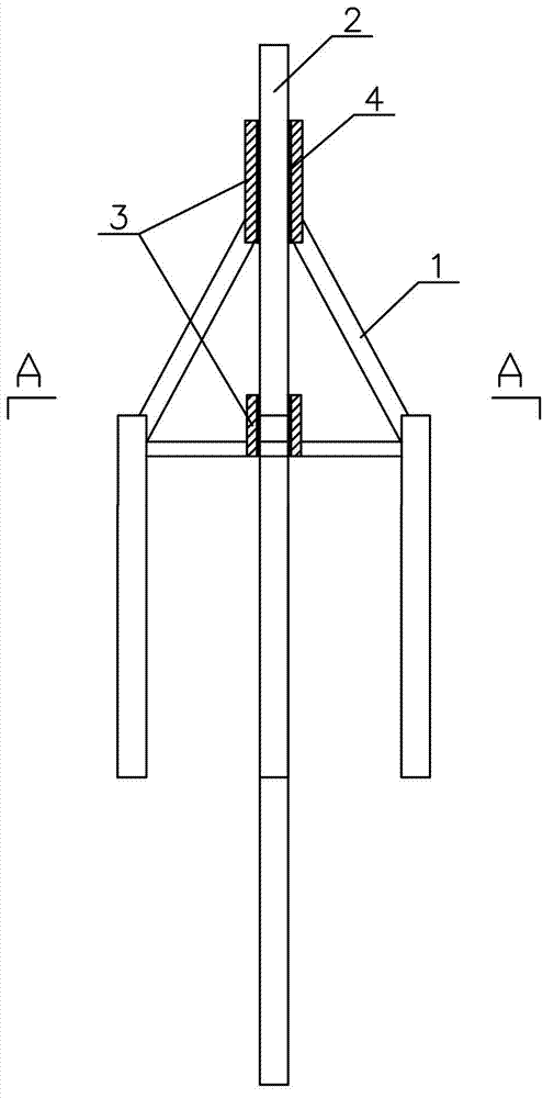
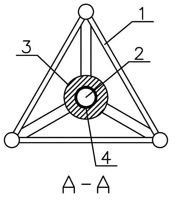
[0020] Such as figure 1 and figure 2 As shown, this embodiment discloses a composite pile foundation structure, which mainly includes a three-pile tripod foundation 1 , a single pile foundation 2 and a connecting section 3 .

[0021] The three-pile tripod foundation 1 includes a truss and three piles. The weight of the truss is 300t; the diameter of the pile is 1.5m, the wall thickness is 20mm, the length is 15m, and the distance between the three piles is 30m.

[0022] The monopile foundation 2 is a steel cylinder structure with a diameter of 3m, a wall thickness of 30mm, and a length of 30m.

[0023] The connection section 3 is two steel cylindrical structures with an outer diameter of 3.2m, which are respectively fixed on the top and bo...


PUM

PropertyMeasurementUnit
Heightaaaaaaaaaa

Abstract

The invention discloses a composite pile foundation structure. Cylindrical connecting sections are respectively arranged in the centers of the top and the bottom of a truss on the three-pile tripod foundation; the upper and lower connecting sections are inserted into a single-pile foundation; the single-pile foundation is fixedly connected with the connecting sections; and welding, grouting connection through a shear key or elastic connection through an elastic body can be adopted. The advantages of definite stress of the single-pile foundation, high soil layer applicability, convenient construction, high horizontal bearing capacity of the three-pile tripod foundation and the like are fully utilized, compared with the independent single-pile foundation or the three-pile tripod foundation, the composite pile foundation structure has the advantages that the integral rigidity, horizontal load resistance, vertical load resistance and bending moment resistance are greatly improved, particularly the stress mode of the single-pile structure is changed, the bending moment load of the fan load on the foundation is effectively realized, and the horizontal displacement of the wind power structure is reduced, so that the pile length, the pile diameter, the wall thickness and the penetration depth of the pile foundation are reduced; and therefore, the material cost is greatly reduced, and the construction process is simple.

Description

technical field [0001] The invention relates to a foundation structure in the construction field, in particular to a pile foundation. Background technique [0002] Offshore wind power structures are high-rise offshore structures with relatively small vertical loads and large bending moments caused by horizontal loads, and require high anti-overturning capabilities. [0003] The monopile foundation structure is a common form of foundation for offshore structures, especially in the field of offshore wind power. It is most widely used in European offshore fields. Its structure is simple and its force mechanism is clear. It is economical to use for wind turbines below 1.5MW. However, due to the weaknesses of the single pile foundation such as poor anti-overturning ability and large horizontal displacement, as the single unit capacity of offshore wind turbines increases to 3MW, 5MW or more, the diameter, wall thickness and penetration depth of the single pile foundation will inev...

Claims


Application Information

Patent Timeline
IPC IPC(8): E02D27/42E02D27/44E02D27/12
Inventor 张浦阳丁红岩练继建乐丛欢
Owner TIANJIN UNIV
Learn More