Anti-seismic lacing bar embedded part

A technology of embedded parts and anti-seismic tension, which is applied in the direction of earthquake resistance, building components, construction, etc. It can solve the problems of scrapped steel holes, scrapped formwork, complex construction operations, etc., to avoid damage, facilitate support and dismantling, and ensure construction quality Effect

Active Publication Date: 2015-02-25
陈绪褚
View PDF7 Cites 0 Cited by
  • Summary
  • Abstract
  • Description
  • Claims
  • Application Information

AI Technical Summary

Problems solved by technology

For buildings with a concrete structure first and then a masonry structure, since the formwork will cut off the tie bars during the construction of the concrete structure, the practice of punching holes in the formwork to penetrate the tie bars and then pouring concrete will damage the formwork, resulting in Abandoned, basically not adopted by the construction party, but at present, the method of post-planting of tie bars is mostly used. The post-planting construction method is mainly based on planting bars with chemical anchoring agents. This post-planting bar has the following problems: 1. 1. The post-planting reinforcement needs to be drilled on the concrete structure, which will damage the structure to a certain extent. 2. The post-planting reinforcement is easy to touch the steel bar during the drilling operation, causing the hole to be scrapped, and the position of the planting reinforcement will change. 3. Because of the tie The reinforcement is basically placed horizontally, and the reinforcement hole is in a horizontal state. The liquid chemical anchoring agent is not easy to fill, which will affect the anchoring effect. 4. The construction operation is more complicated, the quality is poor, and the performance guarantee is relatively low

Method used


Image

  • Anti-seismic lacing bar embedded part
  • Anti-seismic lacing bar embedded part
  • Anti-seismic lacing bar embedded part

Examples


Embodiment Construction

[0023] The specific embodiments of the present invention will be further described below in conjunction with the accompanying drawings.

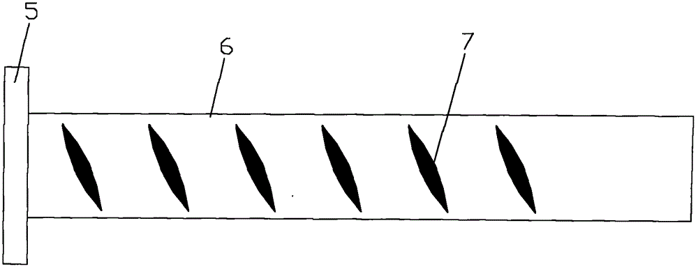
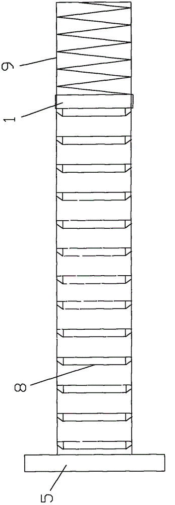
[0024] Such as Figure 1 to Figure 8 As shown, the anti-seismic tie reinforcement embedded part related to the present invention includes a sleeve fixing bracket 10, and the sleeve fixing bracket 10 is connected with the concrete embedded steel bar, and includes a sleeve 6 and a telescopic elastic cap 9. The sleeve 6 is provided with an internal thread 7 or an inverted tooth structure 8; the sleeve 6 is fixed on the sleeve fixing bracket 10, and the stretchable elastic cap 9 is pressed against the pouring concrete formwork.

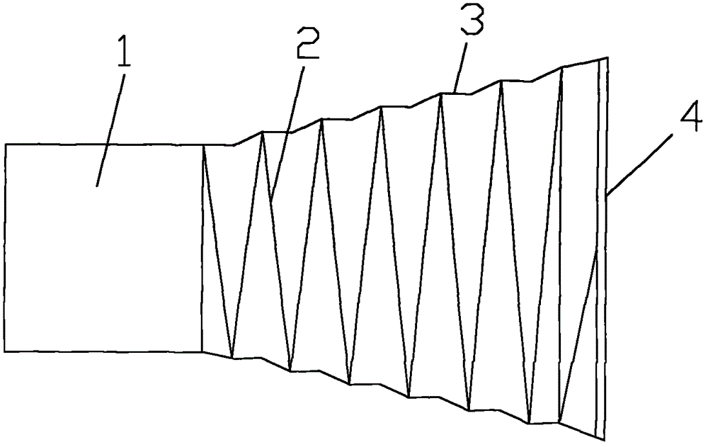
[0025] The flexible elastic cap 9 is columnar or trumpet-shaped, and is composed of a connecting sleeve 1, a shell skin 3, a spring 2 and a cap 4, and the connecting sleeve 1 is connected with the shell skin 3 made of soft material , the spring 2 is arranged in the casing skin 3 , and one end of the spring 2 is pressed...


PUM


Abstract

The invention relates to an anti-seismic lacing bar embedded part which comprises a sleeve fixing support, wherein the sleeve fixing support is connected with an embedded concrete reinforcement; the sleeve fixing support comprises a sleeve and a telescopic elastic cover; an internal thread or a revered tooth structure is arranged in the sleeve; the sleeve is fixed to the sleeve fixing support; and the telescopic elastic cover is propped against a concrete pouring formwork. According to such technical scheme, the anti-seismic lacing bar embedded part is embedded into the concrete without influence to the bracing of the concrete formwork, specifically the anti-seismic lacing bar embedded part is not needed to pass through the formwork, so that the formwork is convenient to brace and disassemble; the formwork has no requirement on hole drilling, so the formwork can be avoided being damaged during constructing; the anti-seismic lacing bar embedded part is served as an approved product which is manufactured according to the design dimension, so that the accuracy of the dimension is higher than that under the method of drilling the hole on the formwork or embedding ribs later; and the anti-seismic lacing bar embedded part can be used as a concealed project to be inspected and accepted together with a reinforcing steel project, therefore, the construction quality can be effectively ensured.

Description

technical field [0001] The invention relates to a pre-embedded part of a concrete structure tie bar, in particular to an embedded part of an anti-seismic tie bar of a reinforced concrete structure. Background technique [0002] At present, in the technical measures of seismic structure of building structure engineering, tie bars are mostly used between concrete structures and walls of masonry and other structures. In masonry structure. For buildings with a concrete structure first and then a masonry structure, since the formwork will cut off the tie bars during the construction of the concrete structure, the practice of punching holes in the formwork to penetrate the tie bars and then pouring concrete will damage the formwork, resulting in Abandoned, basically not adopted by the construction party, but at present, the method of post-planting of tie bars is mostly used. The post-planting construction method is mainly based on planting bars with chemical anchoring agents. Thi...

Claims


Application Information

Patent Timeline
Patent Type & Authority Patents(China)
IPC IPC(8): E04B1/41E04B1/98
Inventor 陈绪褚
Owner 陈绪褚
Why Eureka
Try Eureka