Variable geometry volute device

A volute, geometric technology, applied in engine components, machines/engines, internal combustion piston engines, etc., can solve the problem of not achieving effective engine matching, and achieve the effect of improving turbine air intake efficiency, easy control, and meeting performance requirements.

Active Publication Date: 2013-01-02
康跃科技(山东)有限公司
View PDF7 Cites 4 Cited by
  • Summary
  • Abstract
  • Description
  • Claims
  • Application Information

AI Technical Summary

Problems solved by technology

But in most working conditions, the wastegate volute does not achieve an effective match with the engine

Method used


Image

  • Variable geometry volute device
  • Variable geometry volute device
  • Variable geometry volute device

Examples


Embodiment 1

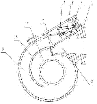
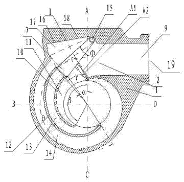
[0055] Example 1, such as figure 2 As shown, a variable geometry volute device includes a turbine volute 1, a volute inlet flow passage 2 is provided inside the turbine volute 1, and a volute inlet flow passage 2 is provided on the turbine volute 1 Connected volute air inlet 9;

[0056] The volute inlet flow passage 2 is provided with a first aerodynamic partition 10, and the first aerodynamic partition 10 divides the volute inlet flow passage 2 into a volute inlet inner flow passage 11 and a volute inlet outer flow passage. , the volute air intake outer flow channel is located on the circumferential outside of the volute air intake inner flow channel 11, and the cross-sectional area of ​​the volute air intake outer flow channel is larger than the sectional area of ​​the volute air intake inner flow channel 11 ;

[0057] A second aerodynamic baffle 12 is provided in the volute air intake outer flow channel, and the second aerodynamic baffle 12 divides the volute air intake ...

Embodiment 2

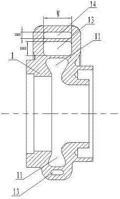
[0083] Example 2, such as Figure 5 ,Such as Image 6As shown, on the basis of Embodiment 1, the cross-sectional shape of the intake regulating valve 7 can also be designed as a rectangular structure, from the center of the intake regulating valve shaft 15 to the end of the intake regulating valve 7 near the volute inlet 9 The ratio of the distance L1 to the total length L0 of the air intake regulating valve 7 ranges from 1 / 4 to 1 / 2.

[0084] The two ends of the air intake regulating valve 7 are inclined-plane structures respectively, and the inner wall 16 of the volute and the first pneumatic partition 10 are respectively provided with mating surfaces matching the two ends of the air intake regulating valve 7 .

[0085] According to the cross-sectional shape of the air intake control valve when it is a rectangular structure, the value of the first critical area A1 at the throat of the turbine volute in the low-speed working condition is the largest, and the third critical ar...

Embodiment 3

[0087] Example 3, such as Figure 8 As shown, on the basis of Embodiment 2, the cross-sectional shape of the air intake regulating valve 7 is designed to be a rectangular structure, and the air intake regulating valve shaft 15 is arranged at one end of the air intake regulating valve 7 close to the first aerodynamic partition 10 .

[0088] The end of the intake regulating valve 7 away from the intake regulating valve shaft 15 has a slope structure, and the inner wall 16 of the volute is provided with a mating surface that matches the intake regulating valve 7 .

[0089] Such as Figure 8 , Figure 9 As shown, the working principle of this embodiment 3 is the same as that of embodiment 1, and the working process of the engine in low-speed working conditions and high-speed working conditions is the same as that of embodiment 1, the difference is that when the engine is in the range of medium-speed working conditions , the air intake adjustment valve shaft 15, driven by the in...


PUM


Abstract

The invention discloses a variable geometry volute device which comprises a turbine volute. A volute air inlet runner is arranged in the turbine volute, a turbine pneumatic separation plate divides the volute air inlet runner into an inner volute air inlet runner and an outer volute air inlet runner, a second pneumatic separation plate is arranged in the outer volute air inlet runner and divides the outer volute air inlet runner into a first branch runner and a second branch runner, and the second branch runner is located on a circumferential outside of the first branch runner. The inner volute air inlet runner is a normally-opened air inlet runner, an air inlet adjusting valve for controlling the first branch runner and the second branch runner to open and close is arranged in the volute air inlet runner close to the position of a volute inlet. The variable geometry volute device achieves variable critical area valve at the position of a throat of the turbine volute through the air inlet adjusting valve so as to effectively meet performance requirements of an engine under each working conditions.

Description

technical field [0001] The invention relates to a volute device, in particular to a device for adjusting the critical area of ​​the volute according to different working conditions of the engine to meet the performance requirements of the various working conditions of the engine, and is mainly used to improve the performance requirements of the engine at a medium speed. A variable geometry volute device belongs to the field of supercharging internal combustion engines. Background technique [0002] In recent years, with the increasingly stringent emission regulations, turbocharging technology has received more and more attention. Under the premise of basically not consuming the effective work of the engine, the turbocharging technology uses the energy of the exhaust gas discharged from the engine to drive the turbine to do work, and pressurizes the intake air of the engine through the compressor; in addition, the turbine has the effect of reducing the noise emitted by the en...

Claims


Application Information

Patent Timeline
IPC IPC(8): F01D25/24F02B37/16
CPCY02T10/144Y02T10/12
Inventor 王航王艳霞范厚传袁道军宋丽华曹怀瑞
Owner 康跃科技(山东)有限公司
Why Eureka
Try Eureka