High-load super transonic axial gas compressor aerodynamic design method

A technology of axial flow compressor and aerodynamic design, applied in the direction of mechanical equipment, machine/engine, liquid fuel engine, etc., can solve problems such as difficulty in suction pipeline layout, decrease in blade strength, increase in number of blades, etc., to reduce design difficulty, Efficient turning and reducing the effect of absolute Mach number

Active Publication Date: 2013-01-02
HARBIN INST OF TECH
View PDF4 Cites 22 Cited by
  • Summary
  • Abstract
  • Description
  • Claims
  • Application Information

AI Technical Summary

Problems solved by technology

[0006] In order to avoid a series of problems caused by boundary layer suction or tandem cascade control means in moving blades, such as difficulty in the layout of suction pipes, decrease in blade strength, and increase in the number of blades, the present invention further provides a high-load supercharger. , Transonic axial flow compressor aerodynamic design method

Method used


Image

  • High-load super transonic axial gas compressor aerodynamic design method
  • High-load super transonic axial gas compressor aerodynamic design method
  • High-load super transonic axial gas compressor aerodynamic design method

Examples


specific Embodiment approach 1

[0024] Specific implementation mode one: as Figure 1~1 As shown in 1, the aerodynamic design method of the high-load super-transonic axial-flow compressor described in this embodiment is realized through the following steps:

[0025] Step 1. High-load aerodynamic design of moving blades:

[0026] The rotor blade is designed with high load and large rotation angle. Under the premise of axial air intake, the outlet of the rotor blade can be axially aligned with the airflow direction (see Fig. 7); at this time, the rotation angle of each section of the rotor blade is equal to the relative airflow angle of the inlet (relative to speed and axial angle), the size of each section rotation angle θ max The value of can be determined by the formula (1); considering the relationship between the inlet axial velocity and the peripheral velocity, the airflow rotation angle on each section of the moving blade can reach 50-65 degrees; at this time, the twisting speed on each section is equa...

specific Embodiment approach 2

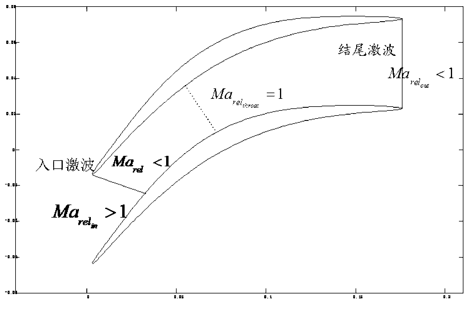
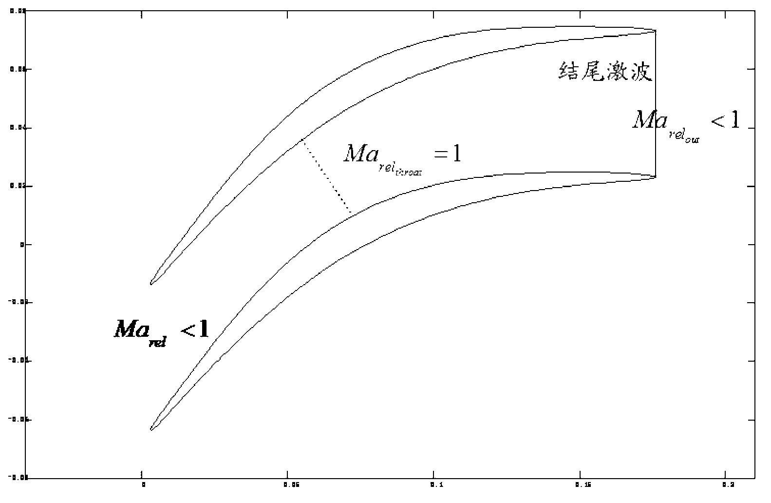
[0033] Specific implementation mode two: combination figure 2 (or image 3 ), Figure 4 and Figure 5This embodiment will be described. Under the condition that the circumferential speed of the moving blade remains constant, the high-load aerodynamic design of the moving blade is carried out by increasing the blade cascade rotation angle. In the case that the incoming flow at the rotor blade inlet is axial air intake, the maximum rotation angle of each section can be calculated by formula 1. At this time, the relative velocity direction of the rotor blade outlet airflow is along the axial direction. The design of the hub can then be combined with the rim, see Figure 4 , so that the meridian flow channel shrinks greatly, and the area of ​​the flow channel decreases. After points C and D, the meridian flow channel tends to be flat, and at this time, the total flow area obtained from the cross-sectional airfoil of each elementary level increases. In addition, in order to e...


PUM


Abstract

The invention discloses a high-load super transonic axial gas compressor aerodynamic design method and belongs to the technical field of axial gas compressors. The problems that pumping pipes are difficult to arrange, the strength of blades are reduced, the number of the blades is increased and the like due to the fact that a control method such as boundary layer pumping or blade lattice series connection is conducted in moving blades are solved. The technical scheme includes that firstly, in a moving bade of a high-load super transonic axial gas compressor, a meridian flowing passage and a blade type design are adopted, so that a blade lattice flowing passage is in a scaling shape, airflow flows quickly in the blade lattice flowing passage, large-turning-angle flowing of airflow in moving blades can be achieved, and at the same time, the absolute mach number of an inlet of a downstream fixing blade is reduced effectively; and secondly, for a downstream fixing blade lattice, the absolute mach number of an inlet is supersonic, flowing separation is controlled through boundary layer pumping, and the airflow is turned back. A specific blade type design scheme and a pumping scheme can be obtained according to an actual situation. The method can be used in aerodynamic design of a gas compressor of a high thrust-weight ratio aero-engine.

Description

technical field [0001] The invention relates to an aerodynamic design method of an axial flow compressor, which belongs to the technical field of axial flow compressors. Background technique [0002] The purpose of the axial flow compressor is to convert the mechanical energy of the impeller into gas pressure energy. Its basic components are composed of rotor and stator. For the compressor, its single-stage pressure ratio is increased, which can effectively reduce the size and weight of the engine and increase the thrust-to-weight ratio of the aeroengine. Generally, there are two main means to increase the pressure ratio of the compressor stage, which is to increase the peripheral speed of the rotor or to increase the turning angle of the rotor blades. [0003] For various types of gas turbines, the current low-pressure fans usually belong to the transonic class. And when the circumferential speed of the rotor is further increased, the low-pressure fan can become superson...

Claims


Application Information

Patent Timeline
Patent Type & Authority Applications(China)
IPC IPC(8): F04D29/38
Inventor 王松涛胡应交
Owner HARBIN INST OF TECH
Why Eureka
Try Eureka