Subsonic velocity vortex blowing type compressor blade

A compressor and subsonic technology, applied in the field of compressors, can solve the problems of limited application conditions, lack of application value, no practical application of turbines, etc., and achieve the effect of increasing blade load

Active Publication Date: 2021-08-06
NORTHWESTERN POLYTECHNICAL UNIV
View PDF11 Cites 3 Cited by
  • Summary
  • Abstract
  • Description
  • Claims
  • Application Information

AI Technical Summary

Problems solved by technology

However, it only appeared in the flat plate experiment, and it was still a conceptual research, and did not appear in the actual application of the turbine
[0007] From the above literature, it can be concluded that air blowing at the boundary layer can effectively suppress the flow separation inside the compressor, and can increase the stage load and pressure ratio of the compressor to a certain extent. However, there are many limitations in its applicable conditions, and it cannot adapt to the A series of complex non-design working conditions in practical applications lead to a lack of application value

Method used


Image

  • Subsonic velocity vortex blowing type compressor blade
  • Subsonic velocity vortex blowing type compressor blade
  • Subsonic velocity vortex blowing type compressor blade

Examples


Embodiment Construction

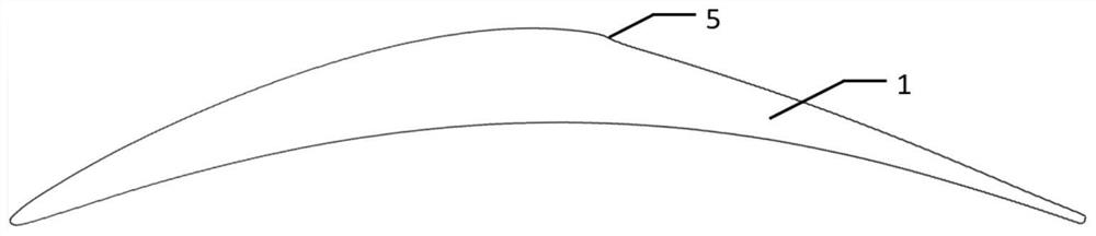
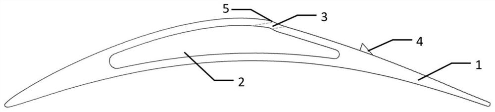
[0044] This embodiment is a subsonic vortex blowing compressor blade. The upper surface of the air blowing compressor blade is the suction surface, and the lower surface is the pressure surface. Between the suction surface and the pressure surface of the blade, there is an air blowing cavity 2 penetrating along the span direction of the blade. A row of air blowing holes 3 is arranged along the spanwise direction on the suction surface, and each air blowing hole communicates with the air blowing cavity. A row of vortex generators 4 is arranged along the spanwise direction on the trailing edge of the suction surface of the blade, and each vortex generator corresponds to each blowing hole one by one. During installation, the leading edges of the vortex generators are aligned with the leading edges of the blades.

[0045] The centers of the orifices of the air blowing holes are located at 58.7% of the chord length of the blade on the suction surface; the distance between the cen...


PUM


Abstract

The invention relates to a subsonic velocity vortex blowing type compressor blade. A row of blowing holes are formed in the suction surface of the blowing type compressor blade in the spanwise direction, and all the blowing holes are communicated with a blowing cavity. A row of vortex generators are arranged at the rear edge of the suction surface of the blade in the spanwise direction, and the vortex generators are in one-to-one correspondence with the blowing holes. Each vortex generator is in a triangular pyramid shape, and the front edge of each vortex generator is consistent with the front edge of the blade in direction. According to the subsonic velocity vortex blowing type compressor blade, a flow control structure is innovated, and the flow separation of the suction surface of the blade is effectively controlled while the load of the subsonic velocity vortex blowing type compressor blade is increased through the blowing cavity penetrating through the blade in the blade expansion direction, the blowing holes formed in the suction surface of the blade and the vortex generators mounted at the rear edge of the suction surface of the blade, so that after high-energy fluid is injected into the blowing cavity, boundary layer separation is effectively restrained, complex working conditions in a compressor are adapted to a certain degree, and the pressure ratio and the load of the compressor are further improved.

Description

technical field [0001] The invention relates to the field of compressors, in particular to a vortex blowing compressor blade. Background technique [0002] The development of modern aviation technology requires aero-engines to have a higher thrust-to-weight ratio. Therefore, it is necessary to further increase the compressor stage load and stage pressure ratio to meet the requirements of a higher thrust-to-weight ratio. However, the working environment inside the high-load compressor is very harsh, and flow separation will inevitably occur inside the compressor under a strong reverse pressure gradient, resulting in flow loss inside the compressor and a decrease in aerodynamic performance. In order to meet the high aerodynamic load requirements of the compressor, researchers have carried out a lot of research on the flow control of the compressor. Current flow control methods are mainly divided into two types: passive flow control techniques and active flow control techniqu...

Claims


Application Information

Patent Timeline
Patent Type & Authority Applications(China)
IPC IPC(8): F04D29/38
CPCF04D29/324
Inventor 曹志远俞樾陈佳窈宋澄郭伟
Owner NORTHWESTERN POLYTECHNICAL UNIV
Why Eureka
Try Eureka