Plasma unmanned aerial vehicle

A technology of plasma and aircraft, applied in the field of aviation, can solve the problems of increasing aircraft weight, increasing aircraft range and flight time, control failure, etc., and achieve the effects of enhancing the ability to resist reverse pressure gradients, inhibiting flow separation, and improving aerodynamic performance

Inactive Publication Date: 2014-03-26
NANJING UNIV OF AERONAUTICS & ASTRONAUTICS
View PDF3 Cites 19 Cited by
  • Summary
  • Abstract
  • Description
  • Claims
  • Application Information

AI Technical Summary

Problems solved by technology

[0002] The attitude control of modern aircraft is mainly realized by the deflection of ailerons, elevators, and rudders, but there are some problems in the hinge mechanism that controls the deflection of the rudder surface: when the rudder surface is flying at a high angle of attack, the efficiency is low, and the control is invalid or even reversed. The controllable flight of the aircraft brings hidden dangers; the hinge mechanism, rudder surface, and hydraulic system increase the weight of the aircraft, which is not conducive to increasing the range and flight time of the aircraft; the existence of rudder surfaces and flat and vertical tails is not conducive to the stealth of the aircraft
However, at present, the intelligent technology is immature or quite complicated, and does not meet the requirements of low cost and high range, and it is difficult to realize it in a short period of time.

Method used


Image

  • Plasma unmanned aerial vehicle
  • Plasma unmanned aerial vehicle
  • Plasma unmanned aerial vehicle

Examples


Embodiment Construction

[0031] Embodiments of the present invention will be described in detail below in conjunction with the accompanying drawings.

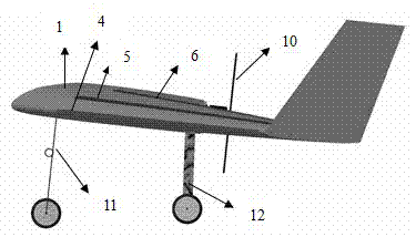
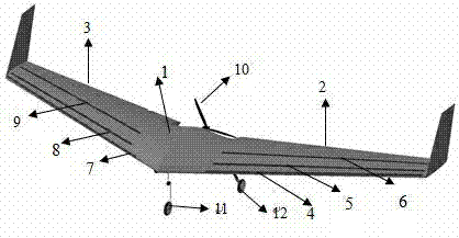
[0032] Such as figure 1 with figure 2 As shown, a plasma aircraft mainly includes a fuselage 1, a left wing 2 and a right wing 3, the left wing 2 and the right wing 3 are respectively connected to both sides of the fuselage 1, and the left and right wings 2 The first plasma exciters 4, 7 are respectively arranged at the leading edge of , 3, the second plasma exciters 5, 8 are respectively arranged at the chord line, and the third plasma exciters 6, 9 are respectively arranged at the maximum thickness. The aircraft also includes a power unit 10 , a front landing gear 11 and a rear landing gear 12 . The aircraft layout is not limited to the flying wing layout, and may be a conventional layout or other layout types.

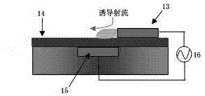
[0033] Such as image 3 As shown, the plasma actuator is a mass barrier discharge plasma actuator, including two asymmetric electrodes...


PUM


Abstract

The invention discloses a plasma unmanned aerial vehicle. First plasma exciters are distributed on the leading edges of a left wing and a right wing of the aerial vehicle; second plasma exciters are distributed in the one fourth positions of chord lines; and third plasma exciters are distributed in the maximum thickness positions. Meanwhile, a miniaturized plasma power supply is designed and integrated into the aerial vehicle, and a switch and relevant discharge parameters of the plasma power supply can be controlled through a program or in a remote control manner. When the plasma exciters start to work, the adverse pressure gradient resistance of a boundary layer is enhanced by means of plasma jet generated by the exciters, a flow field of the upper wing surface of the aerial vehicle can be controlled, and the aerodynamic characteristics of the aerial vehicle are improved; starting of the plasma exciters in the different positions is appropriately adjusted, and aerodynamic moment can be produced, so that the flight attitude of the aerial vehicle can be controlled; and the plasma aerial vehicle has the characteristics that the aerodynamic characteristics are improved, control plane flight controlling is not required, the invisibility is good and the like.

Description

technical field [0001] The invention relates to the field of aviation technology, in particular to a plasma aircraft. Background technique [0002] The attitude control of modern aircraft is mainly realized by the deflection of ailerons, elevators, and rudders, but there are some problems in the hinge mechanism that controls the deflection of the rudder surface: when the rudder surface is flying at a high angle of attack, the efficiency is low, and the control is invalid or even reversed. The controllable flight of the aircraft brings hidden dangers; the hinge mechanism, rudder surface, and hydraulic system increase the weight of the aircraft, which is not conducive to increasing the range and flight time of the aircraft; the existence of rudder surfaces and flat and vertical tails is not conducive to the stealth of the aircraft. [0003] Especially for aircraft with flying wing layout, although the distribution of aerodynamic load is better than that of conventional layout ...

Claims


Application Information

Patent Timeline
Patent Type & Authority Applications(China)
IPC IPC(8): B64C23/00
Inventor 史志伟杜海刘超王海洋戴新喜李铮
Owner NANJING UNIV OF AERONAUTICS & ASTRONAUTICS
Why Eureka
Try Eureka