Direction self adjusting ventilating cowl

A ventilation cap and self-adjusting technology, applied in ventilation systems, space heating and ventilation, heating methods, etc., can solve the problems of low conversion efficiency and large initial investment, saving energy, improving efficiency, and excellent selective moisture permeability The effect of capacity and mechanical strength

Inactive Publication Date: 2013-01-02
SOUTHEAST UNIV
View PDF9 Cites 8 Cited by
  • Summary
  • Abstract
  • Description
  • Claims
  • Application Information

AI Technical Summary

Problems solved by technology

This patent does not directly use natural ventilation wind pressure and heat pressure, because it involves energy conversion, resulting in low conversion efficiency and large initial investment

Method used


Image

  • Direction self adjusting ventilating cowl
  • Direction self adjusting ventilating cowl
  • Direction self adjusting ventilating cowl

Examples


Embodiment Construction

[0023] The specific structure and working process of the present invention will be further described below in conjunction with accompanying drawings.

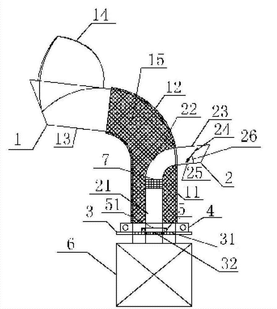
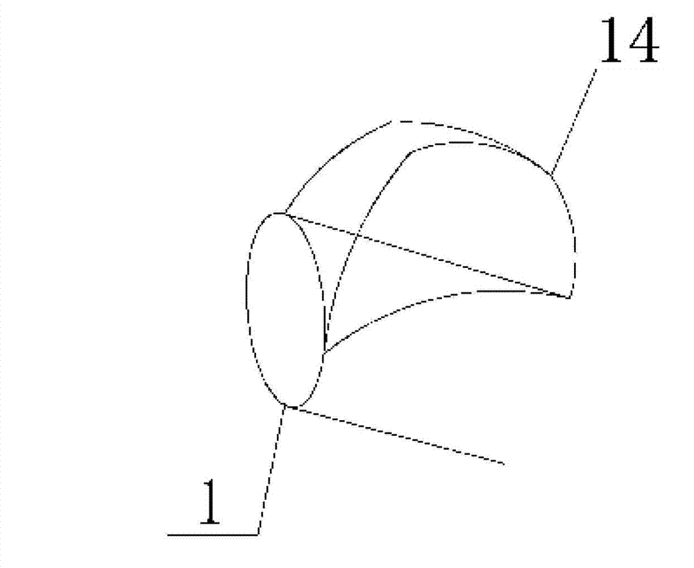
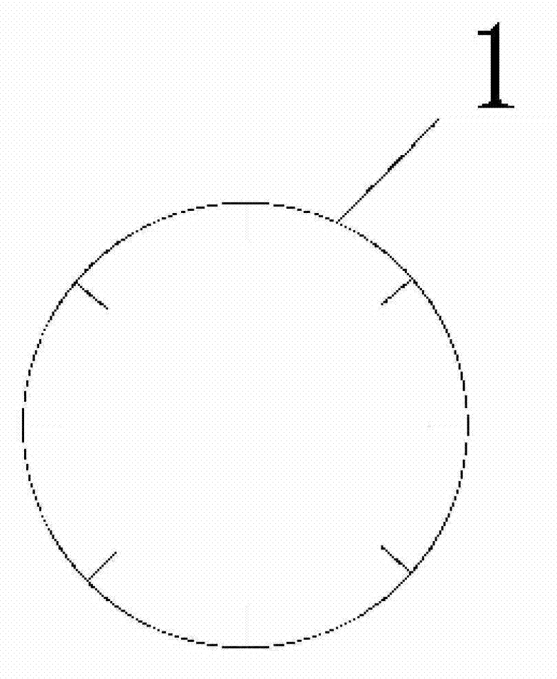
[0024] As shown in the accompanying drawings, the ventilation cap of the self-adjusting direction of the present invention includes an exhaust pipe 1, a vertical exhaust section 11, a transitional exhaust section 12, a horizontal exhaust section 13, a wind cap 14, and a solar heat collection and heat storage material. 15. Air inlet pipe 2, vertical air inlet section 21, transitional air inlet section 22, horizontal air inlet section 23, baffle plate 24, rotating shaft 25, spring 26, bearing seat 3, vent hole 31, second vent hole 32, The first bearing 4, the second bearing 5, the inner hole 51, the total heat exchanger 6, and the air filter 7.

[0025]The bearing housing 3 can be fixed on the roof through threaded connection, and a full heat exchanger 6 is installed under it. The first bearing 4 and the second bearing 5 are fixe...


PUM


Abstract

The invention discloses a direction self adjusting ventilating cowl which comprises an air outlet pipe, an air inlet pipe, a bearing base and a first bearing and a second bearing which are arranged on the upper side of the bearing base. The second bearing is arranged on the inner side of the first bearing and coaxial with the first bearing. A vertical air outlet section of the air outlet pipe is connected with the first bearing, and a vertical air inlet section of the air inlet pipe is located in the air outlet pipe and connected with the second bearing. A first air vent and a second air vent connected with upper side and the lower side of the bearing base are arranged on the bearing base, the air outlet pipe is connected with the lower side of the bearing base through the first air vent, and the air inlet pipe is connected with the lower side of the bearing base through an inner hole and the second air vent. The direction self adjusting ventilating cowl drives indoor air inlet and air outlet through natural wind and hot pressure supplied by solar heat collection and heat accumulation materials so as to achieve bidirectional ventilating. Simultaneously, total heat exchangers are arranged in buildings according to difference in use purposes of the buildings, energy is saved by using temperature difference of air inlet and air outlet to perform heat exchange, and the environment is protected.

Description

technical field [0001] The invention relates to an automatic ventilation energy-saving device applied to buildings, in particular to a self-adjusting direction ventilation cap. Background technique [0002] The current building ventilation devices are mainly driven by the power supply. When the power supply is used, it will consume a lot of power and cause a certain degree of damage to the environment. In recent years, ventilators without power have also been developed, but it cannot be realized simultaneously The purpose of air intake and exhaust has limited effect on building energy saving. Through searching, it is found that the Chinese utility model patent: Pneumatic energy storage heat preservation and dehumidification two-way ventilation cap, patent number: ZL200920071880.6, this patent relates to a ventilation device, which includes an exhaust pipe, an air inlet pipe, a heat exchange box, and a bearing , the components are connected in turn as a whole, the device can...

Claims


Application Information

Patent Timeline
Patent Type & Authority Applications(China)
IPC IPC(8): F24F7/04
Inventor 钱华郑晓红梁文清南旭张宏升
Owner SOUTHEAST UNIV
Why Eureka
Try Eureka