Synchronous control apparatus and synchronous control method

A technology of synchronous control and control section, applied in the direction of digital control, program control, electrical program control, etc., can solve problems such as spindle speed changes, achieve reliable synchronous control, and alleviate impact effects

Active Publication Date: 2013-01-02
ORMON CORP
View PDF6 Cites 19 Cited by
  • Summary
  • Abstract
  • Description
  • Claims
  • Application Information

AI Technical Summary

Problems solved by technology

However, in so-called general-purpose motion controllers, the speed of the main axis may vary greatly
In such a case, synchronous control cannot be started at the synchronous start position

Method used


Image

  • Synchronous control apparatus and synchronous control method
  • Synchronous control apparatus and synchronous control method
  • Synchronous control apparatus and synchronous control method

Examples


no. 1 approach

[0034] Embodiments of the present invention will be described in detail with reference to the drawings. In addition, the same code|symbol is attached|subjected to the same or equivalent part in a figure, and the description is not repeated.

[0035]

[0036] The PLC (Programmable Logic Controller) of this embodiment has an operation control function for controlling the motion of the motor. First, refer to figure 1 , and the system configuration of PLC 1 according to the present embodiment will be described.

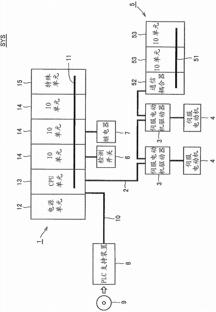
[0037] figure 1 It is a schematic diagram which shows the schematic structure of the PLC system which concerns on embodiment of this invention. refer to figure 1, the PLC system SYS includes a PLC1, a servo motor driver 3 connected to the PLC1 via a field network (field network) 2, a remote IO terminal 5, a detection switch 6 and a relay 7 as field devices. Moreover, the PLC support apparatus 8 is connected to PLC1 via the connection cable 10 grade|etc.,.

[0038]...

no. 2 approach

[0111] In the second embodiment, a further embodiment of a method for synchronizing the master shaft and the slave shaft at a predetermined position when the speed of the master shaft changes from the time of the catch-up operation will be described.

[0112] Figure 7 It is a flowchart showing the operation procedure of the synchronous control in the second embodiment.

[0113] First, the user command value 62 inputs command values ​​of the synchronization start master position SPM, synchronization start slave position SPD, gear ratio GR, target speed VTD, target acceleration ATD, and target deceleration BTD specified by the user (step S101).

[0114] Next, the scheduling unit 63 instructs the start of the follow-up operation of the driven shaft (step S102 ).

[0115] The detection unit 65 acquires the count value (position) of the pulses from the encoder 67 for the main shaft at the time Ts at which the start is instructed, and sets it as the position PM (Ts) of the main sh...

Deformed example 1

[0135] In addition, in this embodiment, as shown in the figure, the cam curve accelerates in a straight line, then becomes a constant speed, and then decelerates, but the present invention is not limited thereto. As the cam curve, for example, a generally known cycloid curve, a trapecloid curve, or the like may be used. Examples of literature on cam curves include "CamDesign and Manufacturing Handbook Second Edition (written by Robert L. Norton INDUSTRIAL PRESS INC2009)", "Mechanics of Mechanics by Mechanics Technician のための実" (by Masao Nishioka, Nikkan Kogyo Shimbunsha, 2003), etc. . In addition, the cam curve can also be represented by a polynomial.


PUM


Abstract

A synchronization control apparatus enables an impact applied to a driven shaft to be alleviated, and synchronization control to be surely started at a synchronization start position. A user command unit (62) specifies a synchronization start position where a main shaft and a driven shaft start synchronization. A cam curve creating unit (64) creates a cam curve. A detection unit (65) detects position information of the main shaft in each control period. A control unit (66) calculates a velocity command value to the driven shaft in each control period, based on the cam curve and the position information of the main shaft up to the synchronization start position, and calculates the velocity command value to the driven shaft in each control period, based on a gear ratio between the main shaft and the driven shaft after the synchronization start position, and the driven shaft is controlled with the calculated velocity command value.

Description

technical field [0001] The present invention relates to a synchronous control device, a synchronous control method, a synchronous control program, and a computer-readable recording medium in which the synchronous control program is recorded, and more particularly to a synchronous control device for synchronously operating a main shaft and a driven shaft according to an arbitrary gear ratio , a synchronization control method, a synchronization control program, and a computer-readable recording medium on which the synchronization control program is recorded. Background technique [0002] Programmable Logic Controller (Programmable Logic Controller: hereinafter referred to as "PLC"), for example, consists of an arithmetic unit that executes a user program, a signal input from an external switch or sensor, and an external relay (relay) or actuator ( Actuator) signal output IO (input output) unit and other multiple units. The PLC executes control operations while exchanging data...

Claims


Application Information

Patent Timeline
Patent Type & Authority Applications(China)
IPC IPC(8): G05D13/62
CPCG05B19/056G05B19/4145G05B19/416
Inventor 细见心一岛村纯儿若年哲司
Owner ORMON CORP
Why Eureka
Try Eureka