Arc fan nozzle used for reducing dust

A technology of nozzle and nozzle body

Inactive Publication Date: 2013-01-09
CHINA UNIV OF MINING & TECH
View PDF5 Cites 2 Cited by
  • Summary
  • Abstract
  • Description
  • Claims
  • Application Information

AI Technical Summary

Problems solved by technology

The main problem of these nozzles is that the water efficiency is low, and the dust production point cannot be fully covered. When the water volume is constant, the coverage area is small, which will bring a series of negative problems.
Take coal mines as an example: roadheaders are mainly used for underground mining operations in coal mines, and the cutting head of the roadheader is relatively large. Generally, a large amount of water spray is required to wrap the cutting head intact, which causes excessive water use and deteriorates the operation. environment, and with the increase of water consumption, the calorific value of coal will decrease, which will affect the quality of coal
Especially in some excavation working faces where the bottom plate is water-absorbent soft rock, the bottom plate will be soft and subsidence due to excessive water for dust suppression, which often affects the normal mining progress and safe production

Method used


Image

  • Arc fan nozzle used for reducing dust
  • Arc fan nozzle used for reducing dust
  • Arc fan nozzle used for reducing dust

Examples


Embodiment 1

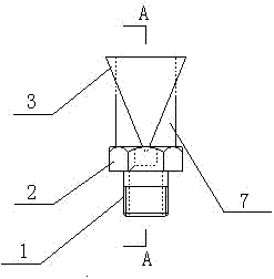
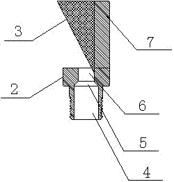
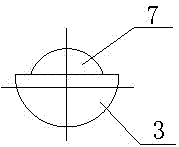
[0018] Such as Figure 1-Figure 3 As shown, the arc fan nozzle for dust reduction of the present invention is mainly composed of a nozzle body 2 and a guide body 3, the bottom of the nozzle body 2 is provided with a threaded joint 1, and the guide body 3 is located at the outlet of the nozzle body 2; The inner hole of the nozzle body 2 described above is divided into an inlet section 4, a gradual throat section 5 and an outlet section 6, which are sequentially connected into a unified body. Both the inlet section 4 and the outlet section 6 are cylindrical pipe sections, and the gradually changing throat 5 is a transition part between the inlet section 4 and the outlet section 6, and its inner diameter is gradually changed. The guide body 3 is a fan-shaped cone, the height of the fan-shaped cone is 1-10cm, and the central angle corresponding to the fan-shaped surface of the fan-shaped cone is between 30°-180°. The nozzle body 2 includes a connector and an extension section 7 p...

Embodiment 2

[0020] Such as Figure 4-Figure 6 As shown, the arc fan nozzle for dust reduction of the present invention is mainly composed of a nozzle body 2 and a guide body 3, the bottom of the nozzle body 2 is provided with a threaded joint 1, and the guide body 3 is located at the outlet of the nozzle body 2; The inner hole of the nozzle body 2 described above is divided into an inlet section 4, a gradual throat section 5 and an outlet section 6, which are sequentially connected into a unified body. Both the inlet section 4 and the outlet section 6 are cylindrical pipe sections, and the gradually changing throat 5 is a transition part between the inlet section 4 and the outlet section 6, and its inner diameter is gradually changed. The guide body 3 is a fan-shaped cone, the height of the fan-shaped cone is 1-10cm, and the central angle corresponding to the fan-shaped surface of the fan-shaped cone is between 30°-180°. The nozzle body 2 includes a connection head and a conduit 8 arrang...


PUM


Abstract

The invention relates to an arc fan nozzle used for reducing dust. The arc fan nozzle comprises a nozzle body with a thread connector, and a flow-guiding body arranged at an outlet of the nozzle body. An inner bore of the nozzle body is divided into an inlet section, a gradient throat section and an outlet section. The flow-guiding body is of a fan-shaped cone, and the height of the fan-shaped cone is of 1-10cm. Dust reducing media at the outlet of the nozzle form into arc fan spray through the flow-guiding body, and drill cutting components such as drills, cutting heads and the like can be preferably wrapped. The diffusing range is wide, and meanwhile, the using quantity of the dust reducing media can be reduced so as to greatly improve the utilizing rate of the dust reducing media. The arc fan nozzle not only can be used for the dust prevention of drills, cutting heads and the like in the drilling and cutting operations, but also can be used on other occasions where the arc fan nozzle is needed. The arc fan nozzle has the advantages of simple structure, uniform spray, small flow quantity, high impact force, high medium utilizing rate and wide practical applicability.

Description

technical field [0001] The invention relates to an arc fan nozzle for dust reduction, and is especially suitable for dust prevention and control in dust-producing operation sites such as drill bits, roadheader cutting heads, coal shearer drums, transfer points, coal bunkers, and quarries. Background technique [0002] In the industrial field, dust has adverse effects on human health, production safety, product quality, economic benefits and many other aspects. It has always been a major issue of national concern. points and difficulties. In recent years, there have been 10,000 new cases of pneumoconiosis every year. By the end of 2011, there were 312,000 cases of pneumoconiosis in coal mining enterprises nationwide, and the detection rate of pneumoconiosis was as high as 7.2%. Experts predict that the total number of pneumoconiosis in my country will continue to rise in the next 10 to 15 years. [0003] In order to prevent and control dust, technical means such as ventilat...

Claims


Application Information

Patent Timeline
Patent Type & Authority Applications(China)
IPC IPC(8): B05B1/26E21B21/00E21C35/22E21F5/04
Inventor 王德明韩方伟汤笑飞王和堂张义坤陆新晓曹凯
Owner CHINA UNIV OF MINING & TECH
Why Eureka
Try Eureka