Cutting machine

A cutting machine and cutter technology, applied in shearing device, pipe shearing device, shearing machine equipment and other directions, can solve the problems of low processing efficiency, troublesome operation, not suitable for batch processing, etc., to ensure length accuracy and reduce labor intensity , the effect of high processing efficiency

Inactive Publication Date: 2013-01-09
SUZHOU DONGLI MACHINERY
View PDF0 Cites 8 Cited by
  • Summary
  • Abstract
  • Description
  • Claims
  • Application Information

AI Technical Summary

Problems solved by technology

[0002] In daily mechanical processing production, sometimes it is necessary to cut some small pipe fittings. The common processing method is to directly cut the pipe fittings directly with shearing tools, but sometimes there are clear requirements for the processing length of the pipe fittings. If the above processing method is used, the length accuracy of the pipe fittings cannot be guaranteed, the operation is troublesome, the labor intensity of the workers is high, and only one pipe fitting can be processed at a time, the processing efficiency is low, and it is not suitable for batch processing

Method used


Image

  • Cutting machine
  • Cutting machine

Examples


Embodiment Construction

[0015] The present invention is described below in conjunction with accompanying drawing.

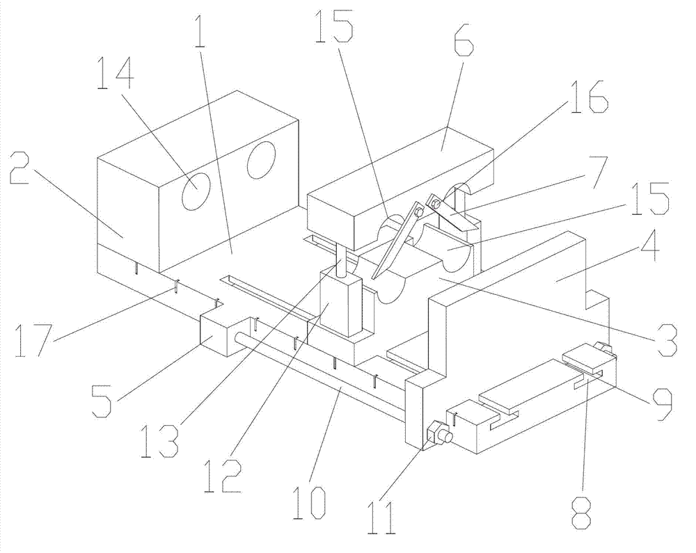
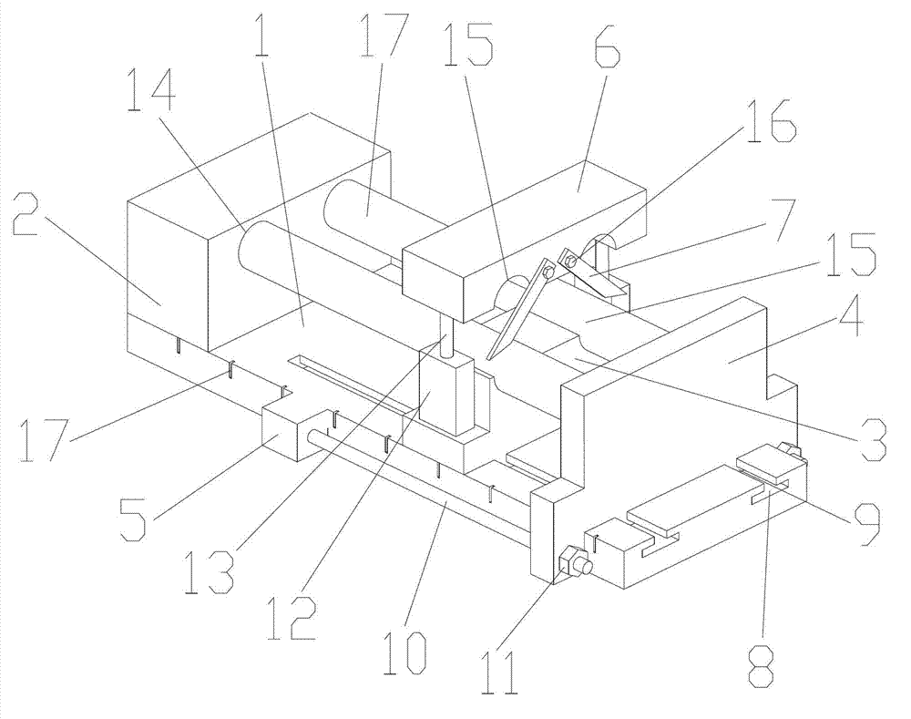
[0016] as attached figure 1 The shown cutting machine of the present invention includes a base plate 1, a fixed block 2, a positioning block 3, a push block 4, a protrusion 5, a connector, a pressing block 6 and a cutter 7; one end of the base plate 1 A fixed block 2 is provided; the base plate 1 is provided with a positioning block 3 and a push block 4 which can slide on the base plate in turn near the fixed block 2; two T-shaped grooves 8 are symmetrically arranged on the base plate 1; the positioning Two T-shaped blocks 9 are symmetrically arranged under the block 3 and the push block 4; the T-shaped block 9 cooperates with the T-shaped groove 8 to realize the movement of the positioning block 3 and the push block 4; Bump 5; said bump 5 is located between the fixed block 2 and push block 4; said bump 5 is connected with push block 4 through a connector; said connector includes a scr...


PUM


Abstract

The invention discloses a cutting machine, comprising a bottom plate, a fixing block, a positioning block, a push block, convex blocks, a connecting rod, a pressing block and cutters, wherein one end of the bottom plate is provided with the fixing block; one part of the bottom plate, which is close to the fixing block, is fixedly and sequentially provided with the positioning block and the push block which can slide on the bottom plate; the convex blocks are arranged at the two sides of the bottom plate; the convex blocks are located between the fixing block and the push block; the convex blocks are connected with the push block through a connecting piece; the positioning block is provided with the pressing block which can move up and down; the fixing block is provided with a plurality of first fixing circular holes; a plurality of fixing semicircular holes are correspondingly arranged on the positioning block and the pressing block; when the positioning block and the pressing block are close, a second fixing circular hole is formed by the two fixing semicircular holes; axes of the first fixing circular holes and the second fixing circular hole are on the same straight line; the pressing block is provided with the cutters which have the same quantity as the fixing semicircular holes; the cutters penetrate through the second fixing circular hole; and a mark groove is arranged at one side of the bottom plate. According to the cutting machine disclosed by the invention, the length precision of a machined pipe fitting can be guaranteed, the machining efficiency is high and the cutting machine is suitable for batch machining.

Description

technical field [0001] The invention relates to a cutting machine, in particular to a cutting machine used for cutting small pipes. Background technique [0002] In daily machining production, sometimes it is necessary to cut some small pipe fittings. The common processing method is to directly cut the pipe fittings directly with shearing tools, but sometimes there are clear requirements for the processing length of the pipe fittings. If the above-mentioned processing method is used, the length accuracy of the pipe fittings cannot be guaranteed, the operation is cumbersome, the labor intensity of the workers is high, and only one pipe fitting can be processed at a time, the processing efficiency is low, and it is not suitable for batch processing. Contents of the invention [0003] In view of the above-mentioned technical problems, the object of the present invention is to propose a cutting machine with simple operation, high processing efficiency and guaranteed length pre...

Claims


Application Information

Patent Timeline
Patent Type & Authority Applications(China)
IPC IPC(8): B23D21/00
Inventor 叶晓峰
Owner SUZHOU DONGLI MACHINERY
Why Eureka
Try Eureka