Optical axis controller of automotive headlamp

A technology for headlights and controllers, which is applied to headlights, vehicle components, optical signals, etc., can solve problems such as inability to improve accuracy, accurately determine the operating state of non-interfering optical axis correction, etc., to improve convenience, The effect of prolonging life and increasing production cost

Active Publication Date: 2013-01-09
MITSUBISHI MOTORS CORP
View PDF8 Cites 11 Cited by
  • Summary
  • Abstract
  • Description
  • Claims
  • Application Information

AI Technical Summary

Problems solved by technology

Therefore, it is difficult to accurately determine the operating state of the correction that does not interfere with the optical axis based on the engine speed
Therefore, the conventional headlight axis controller cannot improve the accuracy for determining the operating state of the vehicle.

Method used


Image

  • Optical axis controller of automotive headlamp
  • Optical axis controller of automotive headlamp
  • Optical axis controller of automotive headlamp

Examples


no. 1 approach

[0039] [1. Device structure]

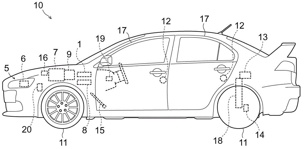
[0040] The optical axis controller of the vehicle headlamp according to the first embodiment is mounted on figure 1 Vehicle 10 is shown. Vehicle 10 is a gasoline powered vehicle driven by engine 7 . The engine 7 generates drive power, which is transmitted to drive wheels of wheels 11 via a transmission (gearbox) 9 and a drive force transmission path (not shown).

[0041] Furthermore, the vehicle 10 includes a pair of left and right headlamps 5 at the front. Each headlamp 5 includes an actuator (adjuster) 6 for adjusting the direction of illumination. The actuator 6 adjusts the optical axis angle in response to the attitude of the vehicle 10 .

[0042] For example, if figure 2Schematically shown, the headlamp 5 includes a vertically movable reflector 5b arranged around a light source 5a. The mirror 5 b has an optical axis 5 c in the lateral direction of the vehicle 10 . The actuator 6 extending or shortening in the horizontal direction (th...

no. 2 approach

[0106] [1. Control block configuration]

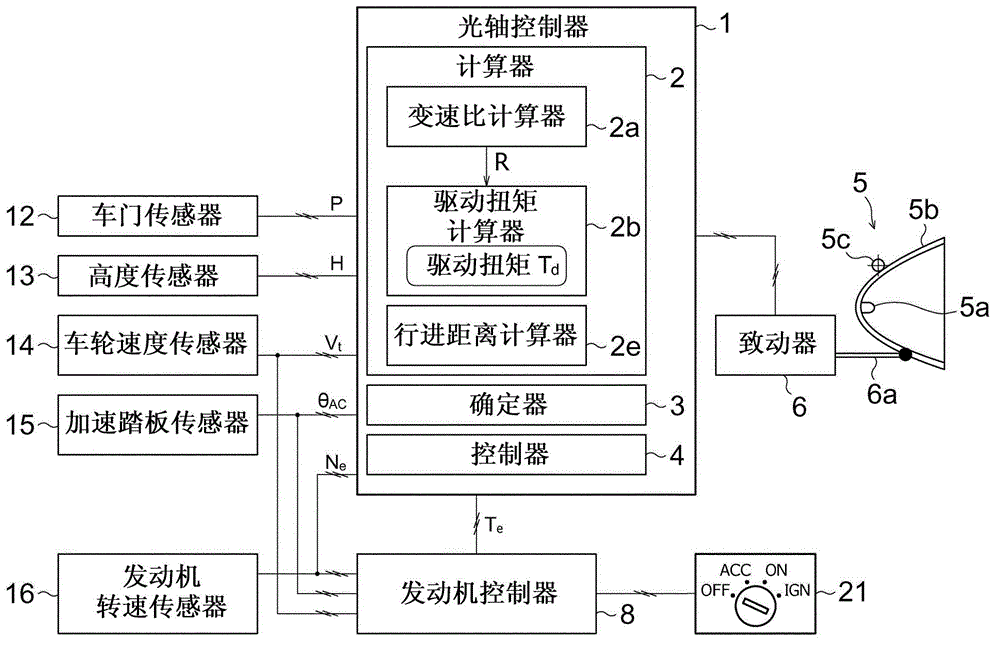
[0107] Such as Figure 5 As shown, the optical axis controller of a vehicle headlamp according to the second embodiment includes a calculator 2 having a different configuration from that of the first embodiment. In this section, the same reference numerals designate the same components as those of the first embodiment, and descriptions thereof are omitted.

[0108] The calculator 2 performs calculations related to the above-mentioned control of the optical axis, and the calculator 2 includes a gear ratio calculator 2a, a drive torque calculator 2b, a resistance torque calculator 2c, a pitching influence torque calculator 2d, and a travel distance calculator 2e . It should be noted that Figure 6 The flow of parameters computed by each component is schematically shown.

[0109] The resistance torque calculator 2 c calculates the resistance torque T while the vehicle 10 is running (during the running mode of the vehicle 10 ) r . Re...

no. 3 approach

[0126] Optical axis controllers are known which are able to adjust the optical axis angle not only during the idle mode but also during other operating modes. Unfortunately, its traditional control logic sometimes fails to determine the vehicle's precise attitude during the vehicle's cornering maneuvers. For example, when a vehicle is running at a constant speed on an expressway ramp (a spiral ramp connecting two roads with a height difference), the vehicle's attitude in the left-right direction is sometimes unstable, even though the vehicle's attitude in the front-rear direction is stable of. Therefore, in order to control the optical axis in an appropriate manner, it is desirable to accurately determine not only the attitude of the vehicle in the pitch direction but also the attitude of the vehicle in the roll direction.

[0127] Therefore, the optical axis controller according to the third embodiment includes a configuration to solve this problem.

[0128] [1. Device conf...


PUM


Abstract

An optical axis controller includes an adjuster(6) which adjusts the optic angle of an automotive headlamp (5), and a drive torque calculator (2b) which calculates the drive torque (T d ) applied to drive wheels of a vehicle (10). The optical axis controller also includes a determiner (3) which determines whether the vehicle (10) is in a static running state or in a dynamic running state, on the basis of the drive torque (T d ). The optical axis controller further includes a controller (4) which permits an adjuster (6) to adjust the optic angle if the determiner (3) determines that the vehicle (10) is in the static running state, and does not permit the adjuster (6) to adjust the optic angle if the determiner (3) determines that the vehicle (10) is in the dynamic running state. This configuration results in accurate determination of the running states suitable for correcting the optical axis.

Description

technical field [0001] The present invention relates to an optical axis controller for automatically controlling the optical axis angle of a vehicle headlamp. Background technique [0002] Optical axis controllers that automatically tilt (control) the optical axis angle of vehicle headlamps in response to changes in the attitude of the vehicle are known. The headlamp controlled by the optical axis controller is provided with an actuator that moves the light source and reflector horizontally and vertically to adjust the angle of the optical axis. For example, if an increase in the number of people in the vehicle lowers the height of the vehicle and moves the headlight's illumination point toward the road, the optical axis controller makes the optical axis angle (depression angle) smaller to allow the light to shine farther and maintain the light's focus. Irradiation distance. This optical axis controller is also called an automatic leveling device. [0003] This optical ax...

Claims


Application Information

Patent Timeline
Patent Type & Authority Applications(China)
IPC IPC(8): B60Q1/115
CPCB60Q1/10B60Q2300/114B60Q2300/136B60Q2300/132
Inventor 林则和八幡忠孝蛭川政刚石塚正隆
Owner MITSUBISHI MOTORS CORP
Why Eureka
Try Eureka