Overline operation crane for high-speed railways

A technology for high-speed railways and cranes, applied in cranes, rescue cranes, etc., can solve the problems of increased weight of the crane itself, difficult operation and maintenance, influence and restriction, etc.

Active Publication Date: 2013-01-09
WUHAN BRIDGE INDUSTRIAL EQUIPMENT COMPANY LTD
View PDF5 Cites 9 Cited by
  • Summary
  • Abstract
  • Description
  • Claims
  • Application Information

AI Technical Summary

Problems solved by technology

However, according to the analysis, when the lifting moment of the crane increases, the height of the fish-bellied girder of the chassis will also increase. Due to the limitation of the railway limit, the design space of this traversing method cannot meet the structural design requirements of the traversing device. At the same time, the crane itself The increase in weight makes the force acting on the railway track and roadbed by traversing the track also exceed the allowable range
The traversing device is installed at the bottom of the crane and carried by the crane itself, which has certain convenience, but in some cases, its operating space is narrow and workers cannot construct, and the mechanism is complicated and difficult to operate and maintain. The mechanism on the surface moves laterally, and the lateral movement of the crane will be affected and restricted by the ground conditions of the subgrade

Method used


Image

  • Overline operation crane for high-speed railways
  • Overline operation crane for high-speed railways
  • Overline operation crane for high-speed railways

Examples


Embodiment Construction

[0021] How to implement the patent of the present invention will be further explained with the accompanying drawings:

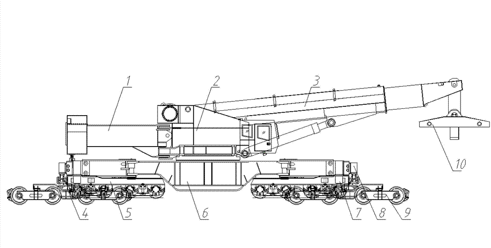
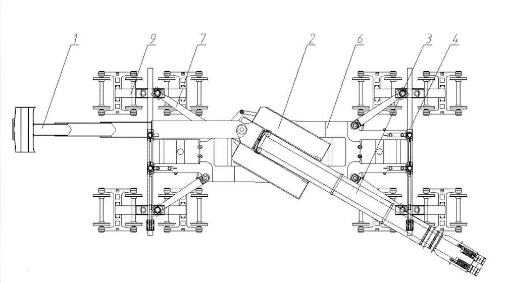
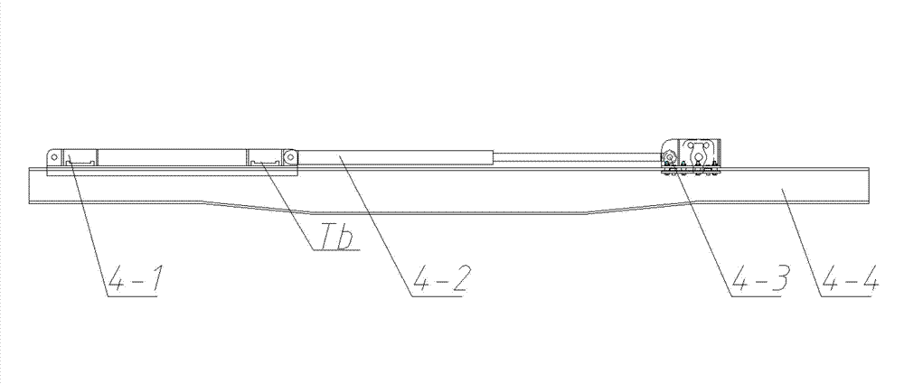
[0022] The high-speed rail crane with the patent of the invention is composed of a railway crane, a traverse mechanism 4, a special high-speed rail spreader 10, and an auxiliary supporting trolley 9. The railway crane includes an upper car and a lower car. The upper car includes a turntable 2, a telescopic boom 3, a slewing mechanism, and a telescopic counterweight 1. The lower car includes a chassis 6, a crane leg 7, a bogie 5, and an auxiliary leg 8. The lower end of the jacking cylinder in the crane leg 7 is a ball head with a spherical hinge structure, which can be matched with the spherical hinge seat on the longitudinal beam of the supporting trolley 9. The hook of the telescopic boom 3 of the crane can be embedded in the web of the upper beam of the special high-speed rail spreader 10, and is connected with the spreader by two pin shafts crossing the web....


PUM


Abstract

The invention relates to an overline operation crane for high-speed railways, belongs to the field of cranes and particularly relates to high-speed railway and rail transit cranes. Two transversing mechanisms including a front transversing mechanism and a back transversing mechanism are respectively erected on four supporting trolleys of a double-line rail, and are in butt joint with the crane through auxiliary supporting legs, and the crane is separated from the original rail line under action of auxiliary supporting leg jacking cylinders, and transverses to the middle of the double-line rail. The front transversing mechanism and the back transversing mechanism moves to be close to the center of the crane together with the front and back corresponding supporting trolleys by retracting effect of the auxiliary supporting legs. Until the auxiliary supporting legs are retracted completely, four crane supporting legs of the crane are unfolded, ball hinges at the tail ends of cylinders of the four crane supporting legs are disposed in ball hinge seats of longitudinal beams of the four supporting trolleys on the double-line rail, and then acting force of the crane to a single-line rail is distributed to the double-line rail successfully, so that operations including overline craning and the like can be carried out for the high-speed railways, and requirements for large-tonnage cranes during rescue and construction on bridge sections of the high-speed railways are met.

Description

Technical field [0001] The invention relates to a cross-line railway crane used for high-speed railways, belonging to the field of cranes, and particularly relates to high-speed railways and rail transit cranes. Background technique [0002] In recent years, high-speed railways and rail transit have developed rapidly, but the supporting construction rescue equipment, especially large-tonnage and high-efficiency railway cranes, has been unable to keep up with their development needs. When the accident happened on the bridge, the bridge deck could not withstand the pressure of the leg supported on the subgrade on the bridge deck when the existing railway crane opened the leg operation. In this case, the design idea of ​​a railway crane with cross-line operation mode came into being. Judging from the existing design ideas, it installs a set of transversal devices under the fish belly beam of the crane chassis, and the rails of the transversal device can be automatically extended by...

Claims


Application Information

Patent Timeline
Patent Type & Authority Applications(China)
IPC IPC(8): B61D15/02
CPCB66C23/50
Inventor 杜斌武李志诚吴元良孙笑萍李建伟刘振营王炜杨威张真
Owner WUHAN BRIDGE INDUSTRIAL EQUIPMENT COMPANY LTD
Why Eureka
Try Eureka