Movable guide rod type reciprocating wing lifting force generation device

A technology for generating devices and guide rods, which can be used in helicopters, motor vehicles, transportation and packaging, etc., and can solve problems such as inability to take off and land vertically, low maneuverability and safety in operation, and complex structures

Active Publication Date: 2013-01-09
广州欣彩电脑耗材有限公司
View PDF5 Cites 20 Cited by
  • Summary
  • Abstract
  • Description
  • Claims
  • Application Information

AI Technical Summary

Problems solved by technology

[0003] Traditional fixed-wing aircraft rely on the fixed wing to generate lift at a relative speed to the air. Although the operation is simple, it cannot take off and land vertically, hover and fly backwards. It has high requirements for the take-off and landing site and requires a long and flat runway ; Although traditional helicopters can take off and land vertically, the blades of the main rotor rotate while advancing with the body when flying forward. The combination of these two movements makes the relative air velocity of the blades asymmetrical on the left and right sides of the rotation plane , to be balanced by the waving movement of the main rotor, it is difficult to control and trim, its structure is complex, and its maneuverability and safety are not high.

Method used


Image

  • Movable guide rod type reciprocating wing lifting force generation device
  • Movable guide rod type reciprocating wing lifting force generation device
  • Movable guide rod type reciprocating wing lifting force generation device

Examples


Embodiment Construction

[0018] Provide the implementation example of the present invention below, and in conjunction with appendix Figure 1-7 To illustrate.

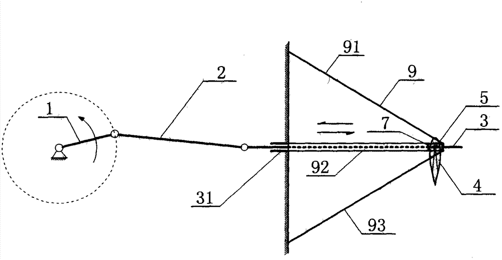
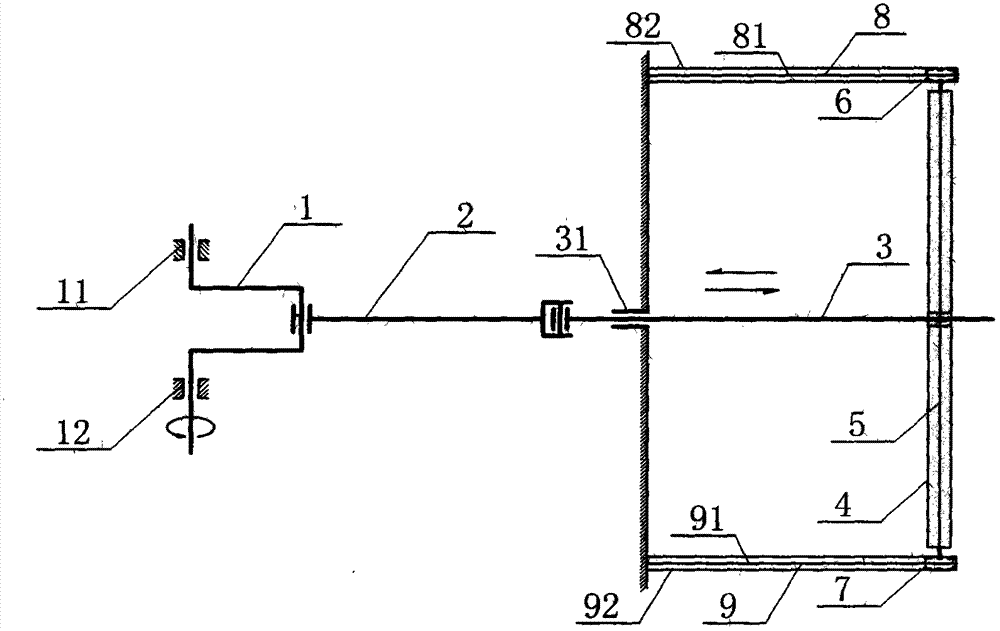
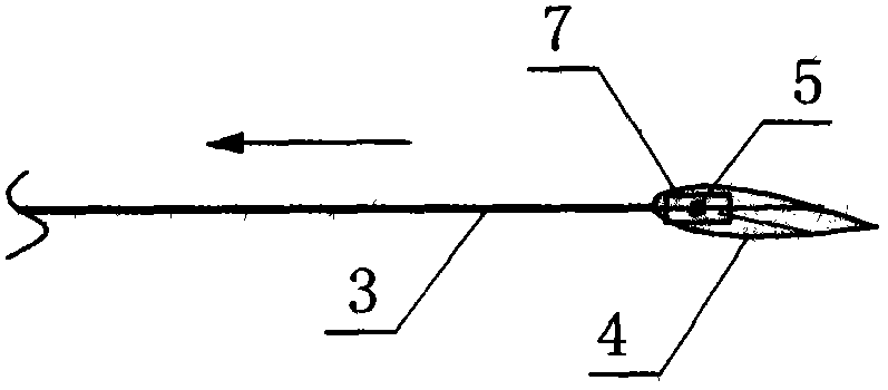
[0019] As shown in the figure, a moving guide rod type reciprocating wing lift generating device of the present invention includes a crankshaft 1, a crankshaft front bearing 11, a crankshaft rear bearing 12, a connecting rod 2, a moving guide rod 3, a guide rod linear bearing 31, and a reciprocating wing 4 and the reciprocating wing drive shaft 5; the crankshaft 1 is installed on the fuselage through the crankshaft front bearing 11 and the crankshaft rear bearing 12, the crankshaft front bearing 11 and the crankshaft rear bearing 12 are arranged on the same horizontal plane, and the left end of the connecting rod 2 is connected with the crankshaft 1 , the right end of the connecting rod 2 is connected with the left end of the moving guide rod 3, the moving guide rod 3 passes through the guide rod linear bearing 31 fixedly installed on the side...


PUM


Abstract

The invention discloses a movable guide rod type reciprocating wing lifting force generation device and belongs to the technical field of an aircraft and a model thereof. The lifting force generation device comprises a crankshaft, a crankshaft front bearing, a crankshaft rear bearing, a connecting rod, a movable guide rod, a guide rod linear bearing, a reciprocating wing and a reciprocating wing driving shaft; and the connecting rod is connected with the crankshaft, the movable guide rod is connected with the connecting rod, the movable guide rod penetrates through the movable rod linear bearing to be arranged in the left-right direction, a run-through hole along the wingspan direction is arranged on the reciprocating wing, the reciprocating wing driving shaft penetrates through the run-through hole of the reciprocating wing, and a gap is arranged at the front edge end of the middle position of the reciprocating wing in the wingspan direction. The crankshaft is driven by power to rotate, so as to drive the movable guide rod to carry out reciprocating motion, and the reciprocating wing driving shaft drives the reciprocating wing to carry out reciprocating motion, so that the upward lifting force is generated. The movable guide rod type reciprocating wing lifting force generation device is simple in structure, convenient to operate and control, higher in efficiency and is used as the lifting device for an aircraft or a model thereof.

Description

technical field [0001] A mobile guide rod type reciprocating wing lift generating device relates to the technical field of aircraft and its models, and can be widely used in the fields of transportation, military affairs, agriculture and forestry, sports entertainment, toys and the like. Background technique [0002] Humans desire to fly freely in the air by driving an aircraft that is simple in structure, safe, reliable and easy to maneuver. [0003] Traditional fixed-wing aircraft rely on the fixed wing to generate lift at a relative speed to the air. Although the operation is simple, it cannot take off and land vertically, hover and fly backwards. It has high requirements for the take-off and landing site and requires a long and flat runway ; Although traditional helicopters can take off and land vertically, the blades of the main rotor rotate while advancing with the body when flying forward. The combination of these two movements makes the relative air velocity of the b...

Claims


Application Information

Patent Timeline
Patent Type & Authority Applications(China)
IPC IPC(8): B64C33/02A63H27/28
Inventor 王志成
Owner 广州欣彩电脑耗材有限公司
Why Eureka
Try Eureka