Cable stripping device

A technology of cables and lenticels, applied in the field of cable stripping devices, can solve the problems of manual separation and automatic feeding, and achieve the effects of reduced load, good locking effect and simple structure

Active Publication Date: 2020-08-14
国网河南省电力公司西峡县供电公司
View PDF5 Cites 5 Cited by
  • Summary
  • Abstract
  • Description
  • Claims
  • Application Information

AI Technical Summary

Problems solved by technology

The peeling machine is originally operated by a single knife in China, but it still needs to be separated manually after cutting, and it cannot be automatically fed
[0003] The Chinese invention patent whose publication number is CN111192724A provides a kind of waste and old cable stripping machine, which comprises a chassis. The upper end of the chassis is fixed with a mounting bracket. There are two thread cutting rollers 1, which are respectively fixed on the first rotating shaft, and two traction rollers are arranged on the side far away from the adjustable dragging mechanism of the thread cutting roller 1, which are respectively fixed on the second rotating shaft , the two ends of the rotating shaft 1 and the rotating shaft 2 are respectively installed on the mounting frame, and the cutting roller 1 and the traction roller located below are driven to rotate by the driving mechanism. There are two sets of height adjustment mechanisms on the mounting frame. The height adjustment mechanisms are used for Adjust the height of the thread-cutting roller 1 and the pulling roller located above, and another set of adjustable thread-drawing mechanism is equipped with two extrusion thread-cutting rollers and two thread-cutting rollers 2 on one side. This invention is suitable for different diameters Cable, but the cut cable core and cable sheath are discharged at the same time, and manual separation is still required

Method used


Image

  • Cable stripping device
  • Cable stripping device
  • Cable stripping device

Examples


Embodiment 1

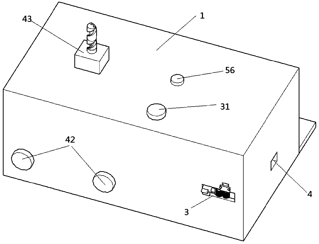
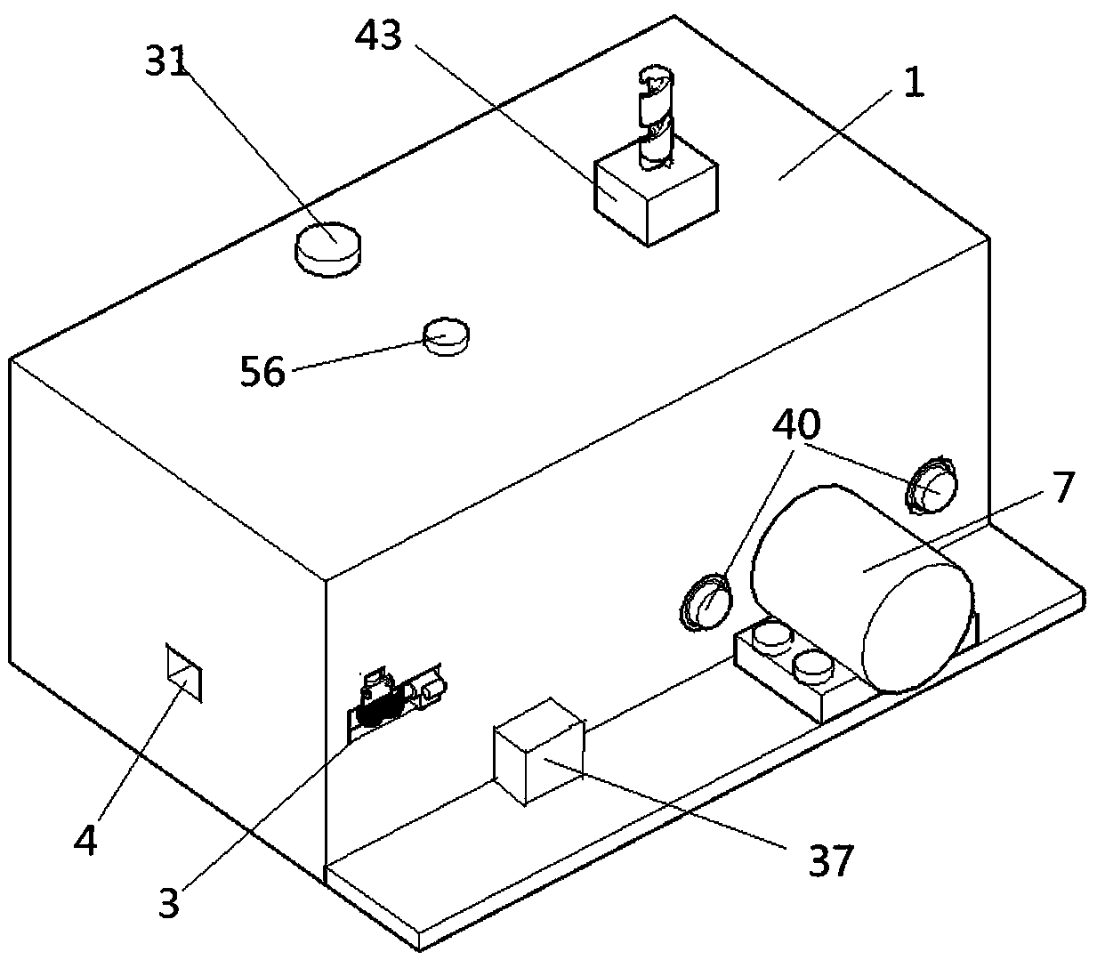
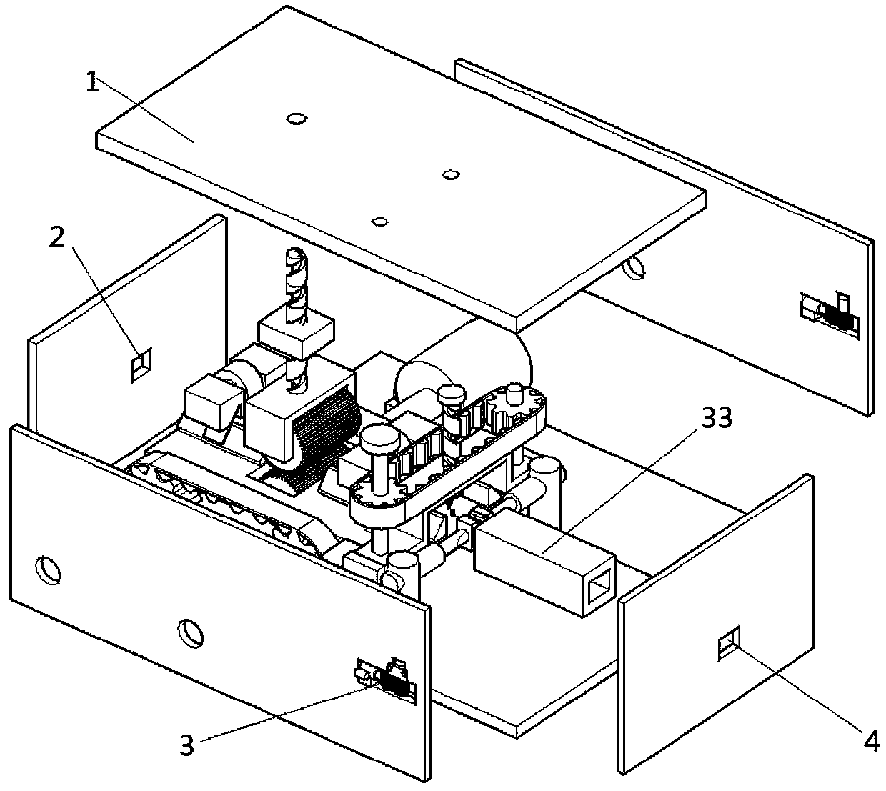
[0043] Such as Figure 1-13 Shown as the first embodiment of the present invention, a cable stripping device includes a fixed box 1, such as figure 1 , figure 2 , image 3 with Figure 4 As shown, the fixed box 1 is a rectangular parallelepiped shell structure welded by eight steel plates. The fixed box 1 is provided with a wire inlet 2, a skin hole 3, and a core hole 4 through a punching machine. There are two skin holes 3 , Are located on both sides of the fixed box 1, respectively, between the wire inlet 2 and the core hole 4, a correction mechanism, a wire feeding mechanism, a cutting mechanism, a separating mechanism, a peeling mechanism and a core tube 33 are arranged in sequence. A fixed plate 18 with a rectangular parallelepiped structure is welded to the inner wall of the left side plate of the fixed box 1, and both sides of the fixed plate 18 are welded to the inner walls of the front and rear sides of the fixed box 1 through side plates.

[0044] Such as Figure 5 wit...

Embodiment 2

[0054] Such as Figure 14 with 15 Shown is the second embodiment of the present invention. The difference between this embodiment and the first embodiment is that two rollers 34 are provided on the sliding plate 19 near the gap. The second roller 34 is a hollow cylinder. The two bearings are fixed with glue, the fixed shaft is welded in the bearing, the two ends of the fixed shaft are welded with connecting strips perpendicularly, and the ends of the connecting strips are welded on the sliding plate 19, the shortest distance between the two rollers 34 and the two sliding plates 19 The distance between the inner walls is the same.

Embodiment 3

[0056] Such as Figure 16 Shown is the third embodiment of the present invention. The difference between this embodiment and the first embodiment is that the receiving box 49 is fixed by glue under the heat insulation plate 44. When the heating plate 13 is tightly attached to the cable sheath, the receiving box and The cable sheath is not in contact. After the heating plate 13 is separated from the cable sheath, part of the cable sheath may be adhered to the concave surface of the heating plate 13. After the heating plate 13 is heated to the melting temperature of the cable sheath, the adhered part melts and drips to the accommodation Inside the box 49; a fan (not shown in the figure) is arranged above the contact part of the heating plate 13 and the cable sheath. The fan is installed on the top wall of the fixed box 1 by screws. The motor of the fan is electrically connected to the output terminal of the PLC37. Control the heating of the heating plate 13 while the PLC37 control...


PUM


Abstract

The invention discloses a cable stripping device. The device comprises a fixed box and also comprises a wire inlet hole, a sheath outlet hole and a core outlet hole formed in the fixed box; a correcting mechanism, a wire feeding mechanism, a cutting mechanism, a separating mechanism and a core outlet pipe are sequentially arranged between the wire inlet hole and the core outlet hole; the correcting mechanism comprises an axial correcting assembly and a radial correcting assembly; the cutting mechanism comprises an upper blade and a lower blade which are oppositely arranged; the separating mechanism comprises two telescopic rods I which are oppositely arranged; the telescopic rod I is arranged on the connecting rod; the connecting rod is driven by a motor II to rotate; an arc-shaped heatingplate is arranged at one end of the telescopic rod; the inner concave surface of the arc-shaped heating plate is tightly connected with two sides of the cable sheath; a sheath outlet mechanism is arranged in the sheath outlet hole; a cable core sheath is cut into two symmetrical parts by the upper blade and the lower blade, the heating plate is bonded with the two parts of the sheath, the telescopic rods I are shortened and rotated, two parts of the sheath are pulled down from the cable and sent out from the sheath outlet hole, a cable core is sent out from the core outlet hole, and the cablecore and the cable sheath are separated and then sent out without later separation.

Description

Technical field [0001] The present invention relates to the technical field of cable recycling, in particular to a cable stripping device. Background technique [0002] In the waste cable recycling industry, with the country's environmental protection requirements, the previous incineration model can no longer be used. The use of the peeling machine improves the production efficiency, and the stripped waste thread can be used as plastic raw materials for secondary use and increase the comprehensive income. The peeling machine was originally operated by a single blade in China, but it still needs to be separated manually after cutting and cannot be fed automatically. [0003] The Chinese invention patent with the publication number CN111192724A provides a waste cable stripping machine, which includes a chassis. The upper end of the chassis is fixed with a mounting frame. The upper end of the chassis is equipped with two sets of adjustable wire pulling mechanisms, one of which is pr...

Claims


Application Information

Patent Timeline
Patent Type & Authority Applications(China)
IPC IPC(8): H02G1/12H01B15/00
CPCH01B15/003H01B15/006H02G1/126H02G1/127H02G1/1275Y02W30/82
Inventor 姚锐刘洋王康王德娟王俊李卓张凡张莹岳彤
Owner 国网河南省电力公司西峡县供电公司
Why Eureka
Try Eureka