Chipping and breaking device

A crushing device and chip technology, which is applied in the field of chip crushing devices for aluminum alloy chips, can solve the problems that there is no aluminum alloy chip briquetting and recycling, chips cannot enter the compression chamber smoothly, and active and effective feeding cannot be formed.

Inactive Publication Date: 2015-09-16
FOSHAN KELI IND EQUIP
View PDF8 Cites 6 Cited by
  • Summary
  • Abstract
  • Description
  • Claims
  • Application Information

AI Technical Summary

Problems solved by technology

However, due to the various shapes and large volume of aluminum alloy chips, the general method cannot form active and effective feeding, resulting in the chips not being able to enter the compression chamber smoothly, and unable to be compressed into a fixed shape of aluminum chips, so that it is impossible to achieve effective energy saving. Environmentally friendly and efficient recycling
In the traditional process, there is no device for briquetting and recycling aluminum alloy chips such as filamentous, flocculent, and spiral

Method used


Image

  • Chipping and breaking device
  • Chipping and breaking device
  • Chipping and breaking device

Examples


Embodiment 1

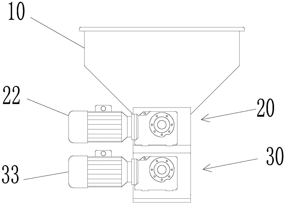
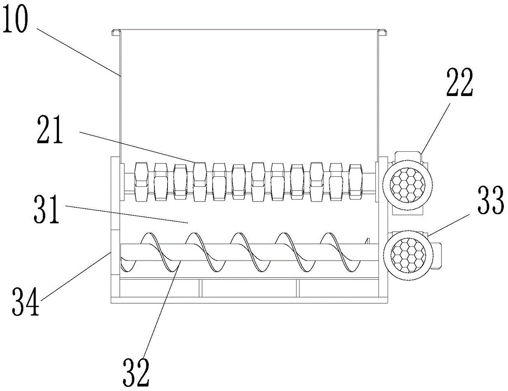
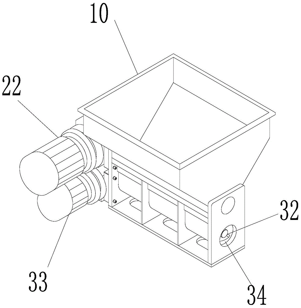
[0016] Such as figure 1 , 2 , 3, 4, and 5, the chip crushing device of this embodiment includes a chip receiving basket 10, a chip device 20, and a discharge device 30. The chip receiving basket 10 is set in a square funnel shape, and the throat is connected to the chip Device 20, the chip cutting device 20 includes a crushing roller 21, a crushing roller reducer 22 for driving the crushing roller 21 to rotate, and a knife-edge plate 23, and the crushing roller 21 is processed with several cutter heads evenly spaced longitudinally, each knife There are 4 cutter heads evenly distributed on the disc, and the knives of two adjacent cutter discs are misaligned with each other. The knife edge plate 23 is installed in parallel with the crushing roller 21, and the edge of the cutter head on the crushing roller 21 and the knife edge plate 23 The gap between the cutting edges is 1 to 3 mm. The chip receiving basket 10 holds the aluminum alloy chips that need to be crushed. In the non...

Embodiment 2

[0018] Such as figure 2 , 4 , 5, 6 This embodiment improves the included angle of the cutting edge of the knife edge plate. The position of the knife edge plate 23 for chips is the edge of the knife edge plate, and the edge of the knife edge plate is set at an angle of 70°. The included angle is 70°, and the cutting edge of the cutter head and the cutting edge of the knife edge plate are set opposite to each other. This included angle can not only ensure that the cutting edge is not easily damaged by the cutting chips, but also ensure the sharpness of the cutting edge of the cutting edge and the cutting edge of the cutting edge plate when cutting chips.

Embodiment 3

[0020] Such as figure 2 , 4 As shown, in this embodiment, in order to smoothly send the chopped chips into the compression chamber, the discharge device 30 is improved. The discharge device 30 is composed of a chip feeding chamber 31, a screw feeding rod 32 installed below the chip feeding chamber 31, and a driving screw. The feed rod reducer 33 for the feed rod 32 to rotate and the discharge port 34 located at the tail end of the screw feed rod 32 are composed. The chip feed chamber 31 is arranged directly below the crushing roller 21 . After being chopped, the chips fall into the chip feeding chamber 31, and then fall on the screw feeding rod 32. The screw feeding rod 32 rotates under the action of the feeding rod reducer 33, and the chips are pressed into blocks and sent out from the discharge port 34. Enter the next process.


PUM


Abstract

The invention relates to the field of breaking devices of metal filling, and particularly to a chipping and breaking device of aluminum product chippings. The chipping and breaking device comprises a chipping and material receiving basket, a chipping device and a material discharging device, wherein the chipping and material receiving basket is designed into the shape of a square funnel, the throat is connected with the chipping device, the chipping device comprises a breaker roll, a breaker roll speed reducer for driving the breaker roll to rotate and a knife edge plate, a plurality of cutterheads are vertically and uniformly processed on the breaker roll at intervals, 4 cutting heads are uniformly distributed on each cutterhead, the cutting heads of two adjacent cutterheads are mutually malposed, the knife edge plate and the breaker roll are installed in a parallel and adjacent manner, and the gap between the cutting edge of the cutting head on the breaker roll and the knife edge plate is 1 to 3 millimeters. The chipping and breaking device is provided with the knife edge plate, the knife edge plate supports aluminum chippings together with the breaker roll when the chipping and breaking device is not in the working state, the load bearing burden of a spiral material feeding stick is reduced, the spiral material feeding stick can not be bent under pressure, and the service life of the spiral material feeding stick is prolonged.

Description

【Technical field】 [0001] The invention relates to the field of crushing devices for metal chips, in particular to a chip crushing device for aluminum alloy chips. 【Background technique】 [0002] Aluminum alloy chips come in various shapes, such as filamentous, flocculent, spiral, strip, flake, etc. If these chips are directly recycled, on the one hand, they are too loose and bulky, requiring a large Moreover, large areas of chips will be severely oxidized in contact with air for a long time; on the other hand, some light and thin chips will be taken away by hot air during remelting, resulting in high recycling costs, large waste, and low efficiency. Therefore, from the aspects of energy saving, environmental protection and high efficiency, aluminum alloy chips need to be pressed into fixed aluminum chip blocks before recycling, so as to facilitate re-casting and reuse. However, due to the various shapes and large volume of aluminum alloy chips, the general method cannot fo...

Claims


Application Information

Patent Timeline
Patent Type & Authority Applications(China)
IPC IPC(8): B02C18/14B02C18/16B02C23/00B02C18/18
CPCB02C18/14B02C18/16B02C18/182B02C23/00
Inventor 孙立国
Owner FOSHAN KELI IND EQUIP
Why Eureka
Try Eureka